EasyManuals Logo

Dometic Elite Control Series User Manual

Dometic Elite Control Series
32 pages
To Next Page IconTo Next Page
To Previous Page IconTo Previous Page
Page #7 background imageLoading...
Page #7 background image
7
EN
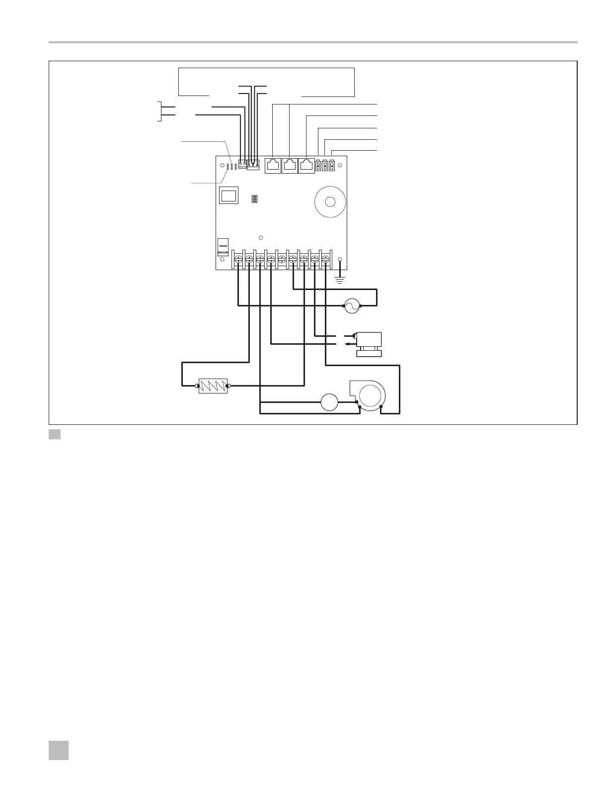
Elite Control Wiring Diagrams
JP1 System Selection Jumper
Display Jacks (for 8- or 6-pin display and cables)
Inside Temperature Sensor Jack
Required Water Inlet Temperature Sensor
Optional Outside Air Temperature Sensor
JP5 Temperature Sensor Selection Jumper
Ground
Fan
Water Valve
Electric Heat Strip
Fan Run
Capacitor
L2
L2
L2
AC
L2
L1
L1
L1
L1
Optional
DC Blower
GND
For Humidistat
For Changeover Switch
COM
COM
0-10 VDC
SMX DISPLAYS ONLY
Optional Water-Out Temperature Sensor
3 CW Wiring Diagram

Questions and Answers:

Question and Answer IconNeed help?

Do you have a question about the Dometic Elite Control Series and is the answer not in the manual?

Dometic Elite Control Series Specifications

General IconGeneral
BrandDometic
ModelElite Control Series
CategoryControl Unit
LanguageEnglish

Related product manuals