EasyManua.ls Logo

Dometic Smart Touch Cabin Control - User Manual

Dometic Smart Touch Cabin Control
44 pages
Print Icon
To Next Page IconTo Next Page
Loading...
COPYRIGHT © 2011-2018 Dometic Corporation. All Rights Reserved.
No part of this publication may be reproduced, translated, stored in a retrieval system, or transmitted in any form or by any means
electronic, mechanical, photocopying, recording or otherwise without prior written consent by Dometic Corporation. Every precaution
has been taken in the preparation of this manual to insure its accuracy. However, Dometic Corporation assumes no responsibility for
errors and omission. Neither is any liability assumed for damages resulting from the use of this product and information contained
herein.
Smart Touch Cabin Control
Installation & Operations Manual
Smart Touch Cabin Control
(shown without bezel)
Dometic Corporation
Rev. 20180628
L-3380 English
P/N 337767

Questions and Answers

  • C
    cmcknightAug 20, 2025
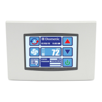
    What to do if the Dometic Control Unit digital display panel is not shown?
    • S
      Sue MartinAug 20, 2025
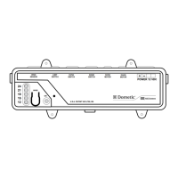
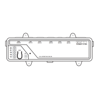
      If the digital display panel of your Dometic Control Unit isn't showing, it could be due to the 8-pin display-cable plugs not making contact (unplugged, dirty, bent, or broken pins). With the power off at the circuit breaker, remove the connector and inspect it. If damaged, replace the connector or the entire display cable.
  • C
    Christina ChenAug 22, 2025
    What to do if my Dometic Control Unit system will not start?
    • N
      Nicholas StewartAug 22, 2025
      If your Dometic Control Unit system won't start, try the following: first, turn the circuit breaker on at the ship’s panel. Then, turn on the control. Check the wiring diagram and correct it if necessary. Ensure the power source (shore/generator) has the correct voltage, and verify wiring and terminals are properly sized and connected using a voltmeter to confirm the power at the unit matches the source. Finally, disconnect the power supply, open the electrical box, and make sure all connections are secure.
  • M
    Matthew PattersonAug 28, 2025
    Why does my Dometic Control Unit system run continuously?
    • D
      David BenitezAug 28, 2025
      If your Dometic Control Unit system runs continuously, try raising or lowering the set point. Make sure all port holes and hatches are closed. Remember that seawater temperature directly affects the air conditioning unit’s efficiency; it can effectively cool in water up to 90°F (32.2°C) and heat (if the reverse cycle option is installed) in water as low as 40°F (4.4°C). Verify the display head location with criteria found in the control manual and install an alternate air sensor if necessary.
  • D
    david19Aug 29, 2025
    How to improve low airflow in my Dometic Control Unit?
    • T
      terrydeniseAug 29, 2025
      To improve low airflow in your Dometic Control Unit, remove any obstructions in the return-air stream and clean the return-air filter and grille. Check for crushed or restricted ducting, ensuring it is as straight, smooth, and taut as possible. If the fan speed is set to Manual Low, press and release the Fan icon until the desired fan speed and airflow are reached. For automatic fan-speed control, press and release the Fan icon until the fan speed indicator shows AUTO.
  • K
    Kenneth StaffordSep 2, 2025
    Why is my Dometic Control Unit not heating?
    • C
      Caroline FrostSep 2, 2025
      If your Dometic Control Unit is not heating, try tapping the reversing valve lightly with a rubber mallet while the unit is in heat mode. Reprogram Reverses Fan Speed in Heat under General Settings.
  • E
    Elizabeth OdomSep 4, 2025
    What does “Low AC Voltage” mean on my Dometic Control Unit?
    • A
      Anthony ParksSep 4, 2025
      If your Dometic Control Unit displays “Low AC Voltage”, it means either the supply voltage is too low, or the voltage is improperly calibrated. Verify the power to the unit with a multimeter. Also, check that the Voltage Calibration under General Settings matches the voltage reading at the unit with a multimeter, and adjust the Voltage Calibration if necessary.
  • L
    Lisa WalkerSep 6, 2025
    What does “Air Sensor Failure” mean on my Dometic Control Unit?
    • T
      Tracey DeanSep 6, 2025
      If your Dometic Control Unit displays “Air Sensor Failure”, it indicates a failed face plate air sensor, alternate air sensor, or display cable. Try unplugging the alternate air sensor if installed, or plug it in if it's not currently installed. You can also try another display cable. Also, check for damaged jack/socket in display head or on the circuit board. Visually inspect to see that pins inside the socket are not bent or corroded. Repair or replace the display or circuit board if needed.
  • J
    Janet CookSep 10, 2025
    What to do if my Dometic Control Unit switches to heat while in Cool Mode?
    • M
      Margaret RivasSep 10, 2025
      If your Dometic Control Unit switches to heat while in Cool Mode, it's likely due to the de-icing feature being enabled because of coil icing up. Reprogram the De-Ice Cycle under the DX settings.
  • R
    Richard AndrewsSep 12, 2025
    Why is my Dometic Control Unit fan not running but the compressor is?
    • D
      Deanna JacksonSep 12, 2025
      If the fan in your Dometic Control Unit is not running but the compressor is, it indicates a failed triac on the circuit board. Send it for repair or call a local service technician.
  • M
    Michael WellsSep 13, 2025
    Why does the Dometic Control Unit fan run continuously when set to cycle with the compressor?
    • J
      John EatonSep 14, 2025
      If the fan in your Dometic Control Unit runs continuously even though it is set to cycle with the compressor, it indicates a failed triac on the circuit board. Send the unit for repair or call a local service technician.

Summary

IMPORTANT PROGRAMMING NOTES TO INSTALLER AND END USER

INSTALLING THE DISPLAY PANEL

CHOOSING THE LOCATION

MOUNTING THE DISPLAY

Provides instructions and dimensions for mounting the display panel.

RECHARGEABLE BATTERY BACKUP

MOUNTING THE OPTIONAL SENSORS

Details the installation of optional remote, outside, service, water, and humidity sensors.

OPERATION

HOME SCREEN ICON FUNCTIONS

Details the specific functions of each icon on the Smart Touch Home Screen.

MODES OF OPERATION

MAIN MENU

CONTROL PARAMETERS

General Settings

Accesses parameters for fan speed, calibration, units, and heat options.

Inside Temp Calibration

Calibrates the ambient sensor within a ±10°F range.

CAN Bus Group ID

Set Point Temperature Differential

Sets the temperature differential for mode switching (1°F or 2°F).

Supply Air Temp Limit

Humidity Sensor Limit Adjustment

Adjusts humidity control set point for DX and CW applications.

DX OPERATIONAL SETTINGS

Compressor Start Delay

Sets compressor staging delay for multi-system installations.

Failsafe Level

Configures protection levels for various fault conditions.

Low Voltage Monitor

Monitors AC input voltage and prevents compressor start if too low.

De-Ice Cycle

Configures the de-icing cycle to prevent evaporator coil icing.

Pump Sentry

Seawater Low Limit Adjustment

Sets the seawater temperature limit for switching to electric heat.

CW OPERATIONAL SETTINGS

PROGRAM SCHEDULER

Display Lock

Set Access Locked by Pin

Sets a security PIN to access different display levels.

TROUBLESHOOTING;COMMISSIONING

System Status

Displays live sensor readings, voltage, frequency, and status.

Help & Information

Provides fault descriptions and QR code for website help.

Commission Procedure

Guides through testing unit inputs and outputs step-by-step.

FAULT HANDLING, HISTORY & RUN HOURS

Fault Help Lookup

Provides help and descriptions for specific fault codes.

QUICK-START OPERATIONS CHECKLIST

MAIN MENU PROGRAMMABLE PARAMETERS

HVAC Control Settings

Lists programmable parameters for HVAC control, including general settings.

DX Operational Settings

CW Operational Settings

Details programmable parameters specific to CW operational settings.

Program Scheduler & Date Time Menu

System Menu, Troubleshooting, Faults & History

TROUBLESHOOTING

GENERAL TROUBLESHOOTING

Provides common problems and their solutions for system operation.

No cooling or heating

DIGITAL CONTROLS TROUBLESHOOTING

FIL (Filter Reminder) is flashing

HPF (High Pressure Fault) is displayed

Details causes and solutions for high-pressure faults.

LAC (Low AC Voltage) is displayed

Explains low AC voltage faults and calibration.

LPF (Low Pressure Fault) is displayed

Addresses low-pressure faults and their troubleshooting.

PLF (Low Pump Flow) is displayed

Explains low pump flow faults and their causes.

Fan is not running

Fan coil is iced

Troubleshoots fan coil icing issues and solutions.

ASF (Air Sensor Failure) is displayed

Explains air sensor failure faults and troubleshooting steps.

MAINTENANCE

SPECIFICATIONS

DIAGRAMS

WIRING DIAGRAMS FOR DX AND CW SYSTEMS

Provides wiring diagrams for DX and CW system configurations.

Dometic Smart Touch Cabin Control Specifications

General IconGeneral
BrandDometic
ModelSmart Touch Cabin Control
CategoryControl Systems
LanguageEnglish

Related product manuals