DIAGRAMS Smart Touch Cabin Control Installation & Operations Manual
40 L-3380 ENGLISH
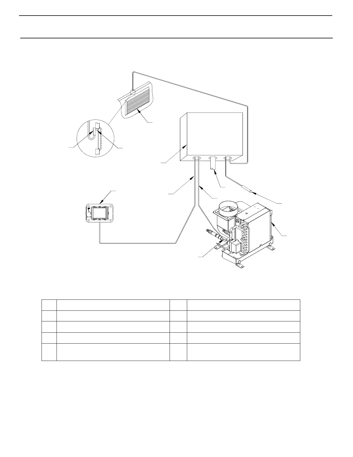
CW SYSTEMS LAYOUT
Figure 3: System Layout Example for Chilled Water Applications
C
HILLED WATER APPLICATIONS DIAGRAM LEGEND
1
Electrical box
6
Water inlet sensor
2
Optional outside air sensor
7
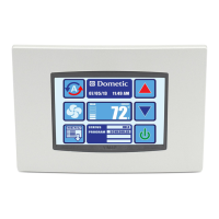
Control display panel
3
AC wire harness
8
8-conductor shielded display cable
4
6-conductor shielded sensor cable
9
Return-air grille
5
Convector assembly
10,
11
Optional remote air sensor
(your choice of 2 installation locations)