EN
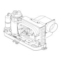
No. Description
9 Ball valve
10 Water outlet
11 Water inlet
12 3-way water valve
13 Heat exchanger
14 Vent valve
2. Connect the pipes to the water manifold.
Follow the manufacture's instructions.
Installing a temperature controller
NOTE Ensure that the temperature controller is surrounded by the return air flow so that the actual ambi-
ent temperature can be read and is not distorted.
Install a temperature controller at the wall 1.5 m above the floor away from the the airflow.
Follow the manufacture's instructions.
Install a remote air temperature sensor behind the air inlet grille.
NOTE Risk of incorrectly measured temperatures
Ensure that the remote air temperature sensor is installed far away from the fan coil filter, the heat ex-
changer and the return air flow.
Installing an expansion tank (optional)
Install an expansion tank in the water circuit (see Fig. on page7).
Follow the manufacture's instructions.
Checking the seawater pump
1. Ensure that a seawater pump is installed under the seawater line.
Follow the manufacturer's instructions.
2. Ensure that a strainer is installed on the seawater pump inlet to prevent debris from being drawn in.
Follow the manufacturer's instructions.
Testing the water connection
1. Fill the fan coils with water using the ball valve.
2.
If present, open the 3-way water valve while filling the water until water flows out of the vent valve (Fig. on
page19, 11).
3. Put the system on 2… 3 barunder pressure by checking the pressure gauge on the sensing line.
4. Check the pressure with the hydrometer attached to the load of the system for a period of 5… 6 h to detect a
loss of pressure.
20