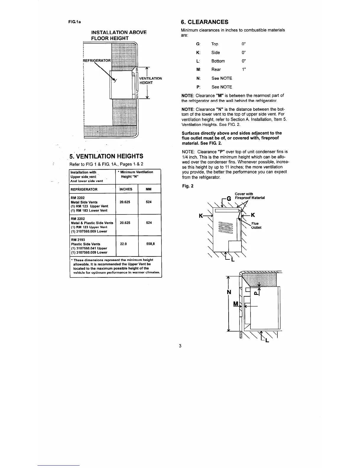
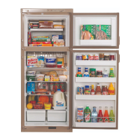
FIG.la
6. CLEARANCES
Minimum clearances in inches to combustible materials
are:
G:
Top
0”
K:
Side
0”
L:
Bottom
0”
M:
Rear
1
II
N: See NOTE
P: See
NOTE
NOTE:
Clearance
“M”
is between the rearmost part of
the refrigerator and the wall behind the refrigerator.
NOTE: Clearance “N” is the distance between the bot-
tom of the lower vent to the top of upper side vent. For
ventilation height, refer to Section A. Installation, Item 5.
Ventilation Heights. See FIG. 2.
Surfaces directly above and sides adjacent to the
flue outlet must be of, or covered with, fireproof
material. See FIG 2.
NOTE: Clearance
“PI’
over top of unit condenser fins is
l/4 inch. This is the minimum height which can be allo-
wed over the condenser fins. Whenever possible, increa-
se this height by up to 11 inches; the more ventilation
you provide, the better the performance you can expect
from the refrigerator.
Fig. 2
Cover with
G Fireproof Material
INSTALLATION ABOVE
.
. .
5.’ “E;JTILATION HEIGHTS
Refer to FIG 1 & FIG. IA., Pages 1. & 2
Installation with
l
Minimum Ventilation
Upper side.vent Height “N”
And lower side vent
REFRIGERATOR ‘INCHES
MM
RM 2202
Metal Side Vents 20.625 524
(1) RM 123 Upper Vent
(1) RM 183 Lower Vent
RM 2202
Metal & Plastic Side Vents 20.625 524
(1) RM 123 Upper Vent
(1) 3107560.009 Lower
RM 2193
Plastic Side Vents
(1) 3107560.041 Upper
(1) 3107560.009 Lower
22.0 558,8
l
These dimensions represent the minimum height
allowable. It is recommended the Upper Vent be
located to the maximum possible height of the
vehicle for optimum performance in warmer climates.