18
Installation
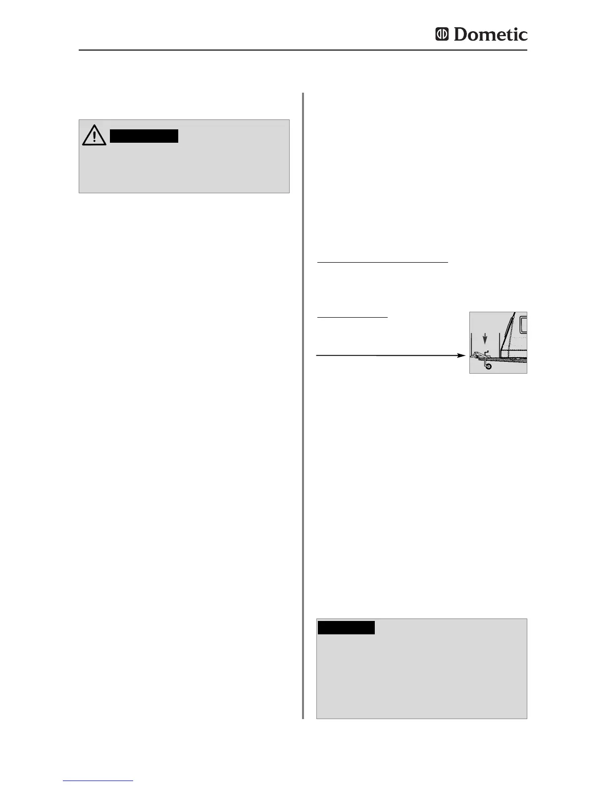
Fig. 34
The electrical installation must be in
accordance with the national regulations
of the respective countries.
The connection cables must be routed in
a way to prevent contact with hot
components of the unit/burner or with
sharp edges.
Changes to the internal electrical instal-
lation or the connection of other electri-
cal components (e.g. external fan) to the
internal wiring of the appliance will ren-
der the e1/ CE admittance as well as any
claims from warranty and product liabili-
ty void!
* Specialised personnel are accredited experts who are
able, by virtue of their training and knowledge, to vouch
for the correct installation.
4.9 Electrical installation
The electrical installation shall be carried
out by qualified personnel only.
WARNING!
4.9.1 Mains connection
The power should be supplied by a pro-
perly grounded socket outlet or a groun-
ded non-detachable connection. Where
a socket outlet with mains supply is
used, the outlet must be freely accessi
ble.
Should the connection cable be dama
ged, have it replaced by Dometic
Customer Services or by qualified per
sonnel to avoid hazards.
We recommend leading the power supply via
a board-side fuse protection.
4.9.2 Battery connection
The machine's 12V connection cable is con-
nected (observing correct polarity) to a termi-
nal strip. The wiring for the heating element
(refer to A, B wiring diagram connections; con-
nection cable white/red) must be direct and by
the shortest possible route to the battery or
electric generator.
Cable cross sections and cable lengths :
Motorcaravan & Caravan (inside)
4 mm
²
< 6 m
6 mm
²
> 6 m
Caravan (outside)
min 2,5 mm
²
(EN1648-1)
2,5mm²
Provide a 16 A fuse to protect on-board 12
V circuit.
In order to ensure that the 12V power supply is
shut off when stopping the engine (otherwise
the battery would discharge within a few
hours), perform the power supply to the hea-
ting element (cf. page 20, connection A/B in
wiring diagram) in a way to have the 12V sup-
ply only live while the vehicle ignition is swit-
ched on.
The connection C/D (interior light, cable black
/ violet) must be permanently provided by a
12V DC power supply to be protected by a 2A
fuse.
If the appliance is installed in a caravan
the respective leads for the 12V+ and 12V-
connections A/B and C/D must not be
connected to each other on the caravan-
side (EN 1648-1).
CAUTION!
 Loading...