Do you have a question about the DoorBird D21x Series and is the answer not in the manual?
Remove all cables from the multi user module prior to module replacement.
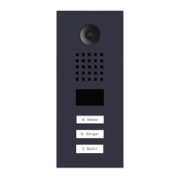
Connect the red cable from the door station to the multi tenant module.
Connect the yellow cable of call buttons to the multi tenant module (e.g., #1, #2).
| Category | Intercom System |
|---|---|
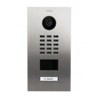
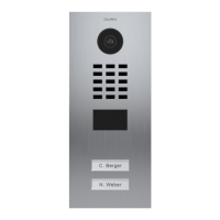
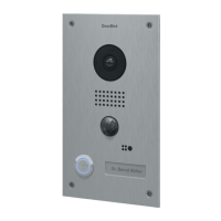
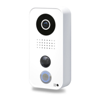
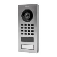
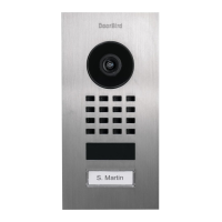
| Series | D21x Series |
| Night Vision | Yes |
| Door Release | Yes |
| On-device Storage | No |
| Field of View | 180 degrees |
| Connectivity | Wi-Fi, Ethernet |
| RFID | Optional |