PROGRAMMING
Fig. 3. Connection of electrical lock
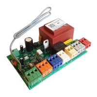
Table 3. Control board terminals (fig. 1, 2, 3)
Terminal Function
(N, L) XP3 Connection of the AC supply voltage, 220 V/50–60 Hz
N Power (neutral)
L Power (line)
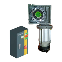
Motor (M-L2, M-L1, M-N) XP5 Electrical motor connection
M-N Common drive wire (blue wire)
M-L1 Direction of the drive movement — open (black wire)
M-L2 Direction of the drive movement — close (brown wire)
XP2 control unit Switch connection
Open Opening
Close Closing
GND Ground
XP6 Connection of the control contacts of an external receiver or a key-button
XP1 Output of constant unstabilized voltage, +12 V
Electrical lock
Transformer
220 × 12, 15 W
220V, 50 Hz
220V
AC 12 V
5. PROGRAMMING
5.1. CONTROL UNIT OPERATING MODES
1. Standby mode. Connecting the control unit to the mains puts the device in the standby mode where it remains until a control
command is given from a remote control or a key-switch; or until switching to programming mode.
9
 Loading...