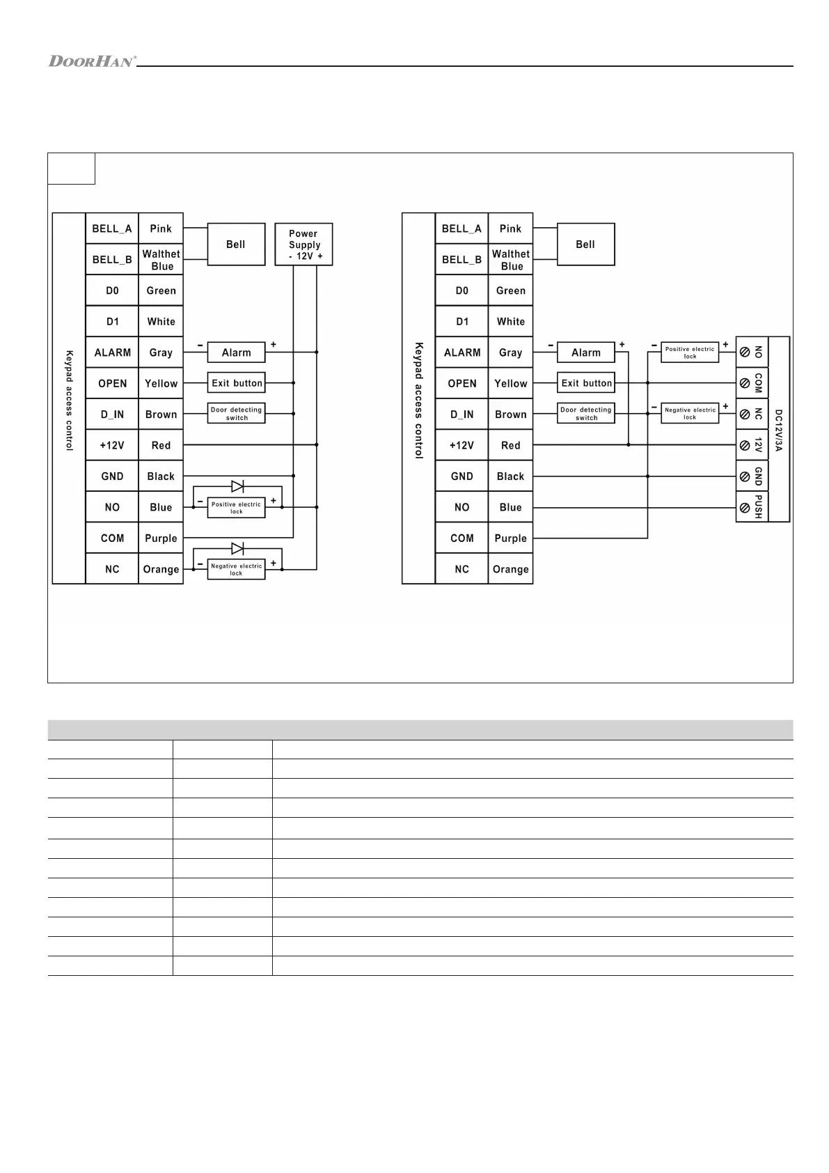
General power supply diagram Special power supply diagram
ELECTRICAL CONNECTIONS
2. ELECTRICAL CONNECTIONS
2.1. CONTROL UNIT WIRING
FIG. 1
Colour Function Description
Pink BELL_A Bell connection (Output 1)
Light blue BELL_B Bell connection (Output 2)
Green D0 WG output D0, connection of external reader control contacts
White D1 WG output D1, connection of external reader control contacts
Grey ALARM Negative signal (positive signal is connected to 12 V+)
Yellow OPEN One end to the output push-button (the other end is connected to GND)
Brown D_IN One end to the magnetic switch (the other end is connected to GND)
Red 12V+ 12V + direct current controlled input power
Black GND 12V - direct current controlled input power
Blue NO Normally open relay
Purple COM Common relay contact
Orange NC Normally closed relay
Table 3. Control unit terminals
10