5
WARNING! RISK OF INJURY!
Have a qualified technician lay the 380-400 V AC cables. The cables must be laid in protective corrugated tubes. Avoid
contact of cables and moving parts of the gate. In case of supply cable damage, use the suitable type of the cable.
INSTALLATION
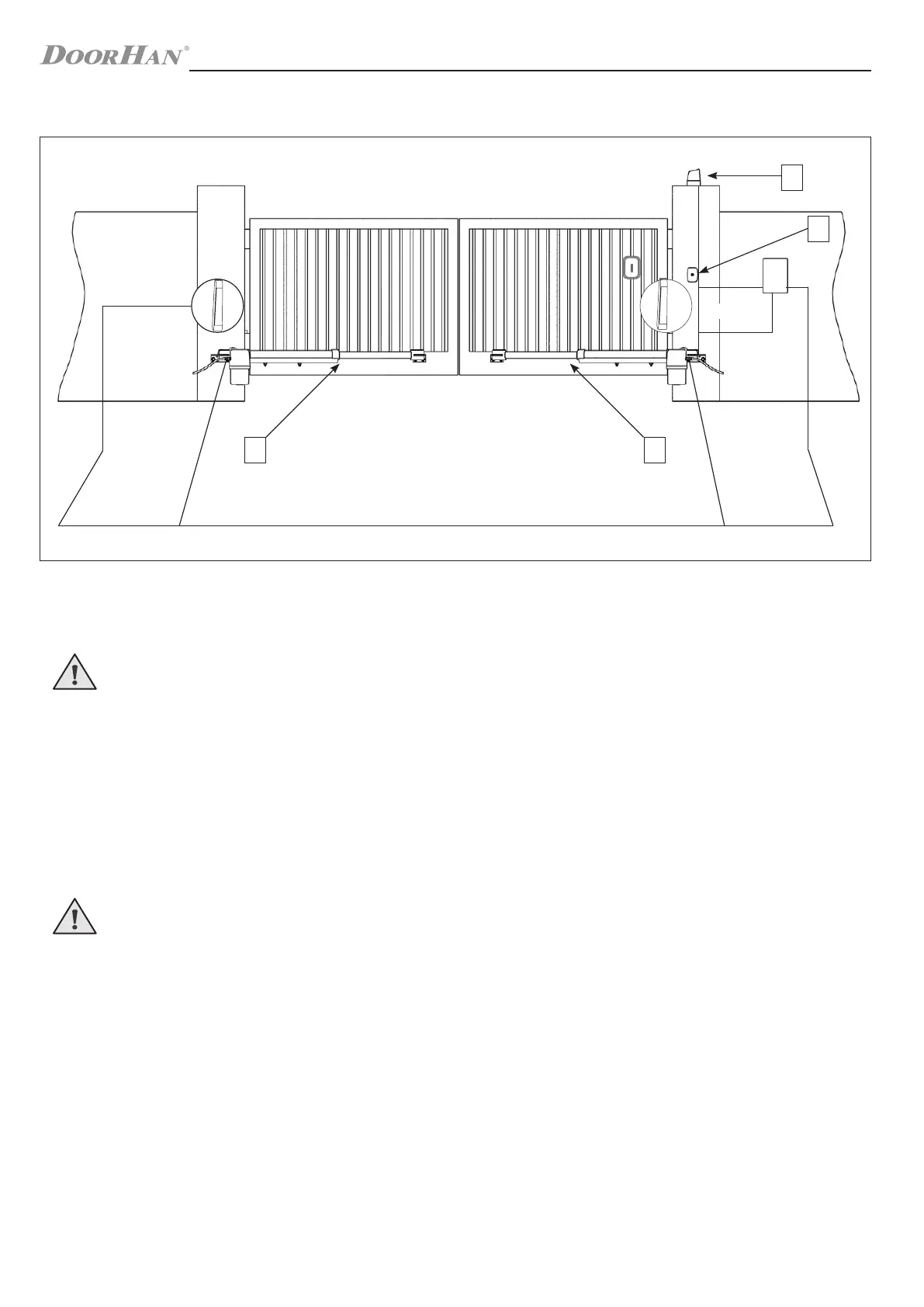
4.2. Scheme of operator installation and cable laying
Cables necessary for installation of Swing-4000 and accessories (if available):
Cable 2 × 0,5 mm
2
(photocell transmitter, step-by-step control button).
Cable 4 × 0,5 mm
2
(photocell receiver).
Cable 4 × 1,5 mm
2
(power supply).
Cable 3 × 0,5 mm
2
(limit switches).
Use cables with appropriate insulation.
WARNING! Use 4 × 1,5 mm and 3 × 0,5 mm cables to connect the operator.
It is recommended to use 4 × 1,5 mm cable to connect the operator motor, and 3 × 0,5 mm cable to connect the limit
switches.
Connect the operators motors to the following terminals of the control board: OP (black), CL (brown), COM (blue) (М1)
and OP (black), CL (brown), COM (blue) (М2) respectively.
Limit switches should be also connected per the colour coding to the control board (COM — blue; OP — black; Cl —
brown).
Supplied capacitors should be connected to OP and CL (M1) and OP and CL (M2) terminals of the control board re-
spectively.
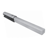
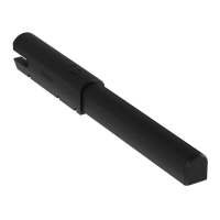
1. Operator
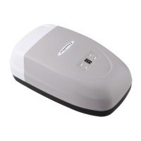
2. Control unit
3. Photocells (option)
4. Signal lamp (option)
5. Key-switch (option)
4 × 1,5
3 × 0,5
4 × 0,5
2 × 0,5
2 × 0,5
1 1
5
4
3
2
3
4 × 1,5
3 × 0,5
 Loading...