1835-067-A-9-18
5
SECTION 1 - INSTALLATION
Prior to installing the telephone entry system, we suggest that you become familiar with the instructions, illustrations, and wiring guidelines in
this manual. This will help insure that you installation is performed in an efficient and professional manner.
Order your telephone line to be installed at least two weeks prior to the planned telephone entry system installation date. This will assure
that a phone line is available when the unit is installed. The telephone company will require the following information from you:
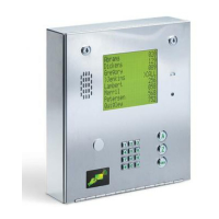
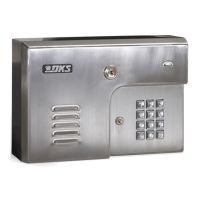
There are different ways to mount the 1835/1837 (On a wall, in a wall, attached to a architectural style post, kiosk, etc). They need a telephone
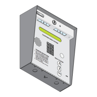
line, power and communication wires run to them in conduit or inside a architectural style post. Feed all of the wires through the back or
bottom of the entry system using the existing knock-outs provided in the enclosures. DO NOT make any new holes in the enclosure to feed
wires through. Keep ALL the entry system’s wires away from any existing high voltage power wires a minimum of 6” to help prevent any noise
and hum pickup in the system’s phone line. The system MUST also be properly grounded to function correctly.
WARNING If this telephone entry system is used to control a vehicular gate with an automatic gate operator, the telephone entry system
must be mounted a minimum of six (6) feet away from the gate and gate operator, or in such a way that the user cannot come into
contact with the gate or gate operator when using this entry system.
The telephone entry system contains a number of static sensitive components that can be damaged or destroyed by static discharges during
installation. Discharge any static prior to removing the circuit board by touching a proper ground device. GREAT care must be taken after
removing the components from the enclosure to protect them throughout the installation. Carelessness on your part is NOT covered under
warranty.
Make sure ALL dirt, metal or wood debris is removed from inside the enclosure after mounting it. A through cleaning of the enclosure is
needed before re-installing the components back into the system and wiring it. Any debris left inside could damage the control board and
cause the telephone entry system to malfunction during operation.
Caller ID: You may want to order caller ID blocking from the telephone company for the entry system phone line. Without caller ID blocking,
residents with the proper phone equipment WILL BE ABLE to identify the telephone number that the telephone entry system is installed on.
This may or MAY NOT be desirable.
Call Waiting: Residents may order call waiting from their local telephone company AFTER the system has been installed. They can avoid
missing calls coming from the telephone entry system while they are using their phone (No busy signal).
1.1 General Installation
Type: Touch Tone, Loop Start
Ringer Equivalence: 0.0 A
Jack Type: RJ11C
FCC Registration (US): DUF6VT-12874-OT-T
DOC (Canada): 1736 4528 A
Electrical Listing: Complies with UL 294 - ETL Listed
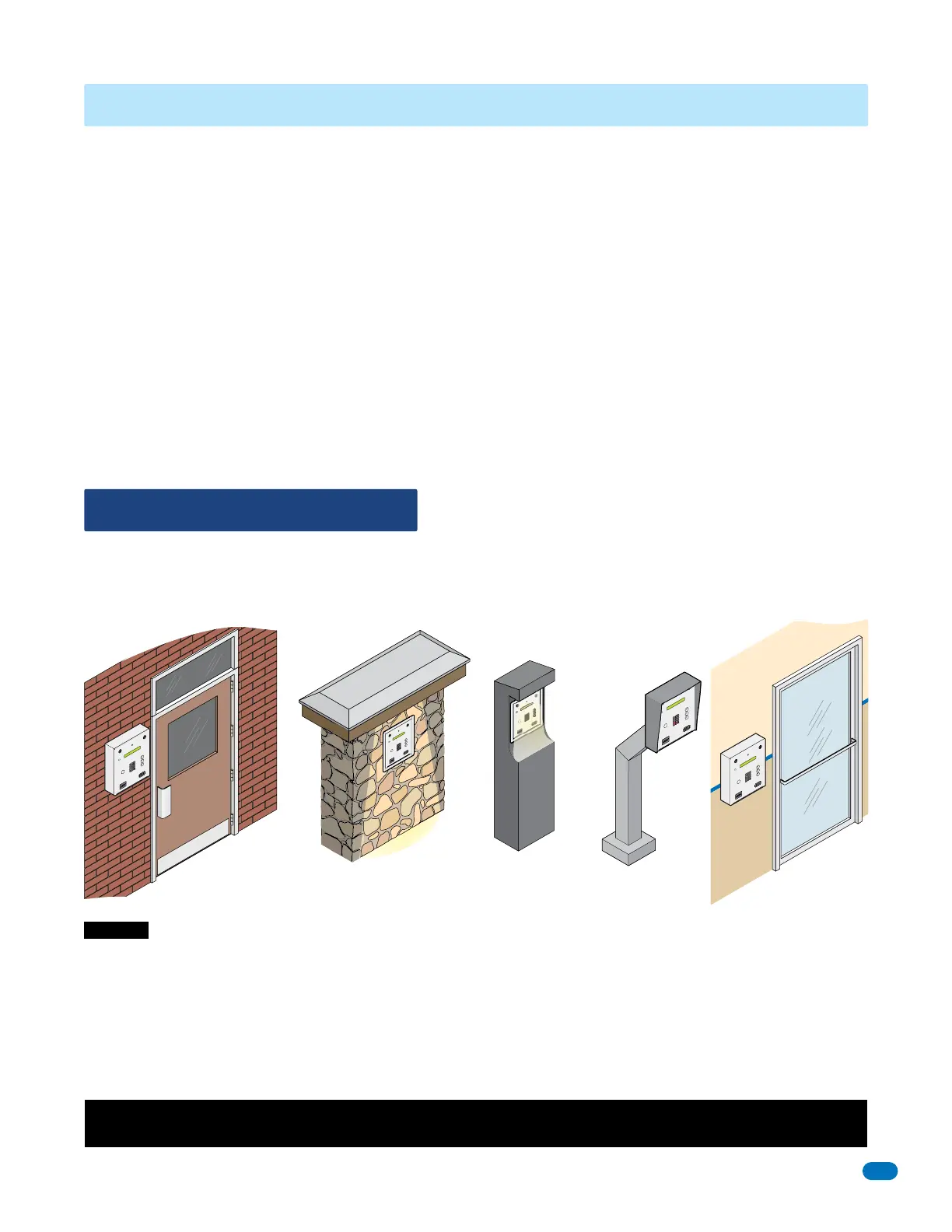
On a Architectural
Style Post
(Optional Hood Shown)
On an Outside Wall
On an Inside Wall
In a Lighted Kiosk
(Optional Flush
Mount Kit Shown)
DoorKing Self-Standing
Lighted Kiosk,
(Optional Flush
Mount Kit Required)
Included with the system is an extra random keyed cabinet lock. If desired, for added security against unauthorized entry into the system,
the standard lock may be replaced with the random lock. Note: DoorKing cannot replace this specific lock or keys if lost.
Destructive Attack: Level I (Level II with optional hood installed)
Line Security: Level I
Endurance: Level IV
Standby Power: Level I
7
8
9
0
4
5
6
1
2
3
C
A
L
L
Z
A
7
8
9
0
4
5
6
1
2
3
C
A
L
L
Z
A
7
8
9
0
4
5
6
1
2
3
CA
L
L
Z
A
7
8
9
0
4
5
6
1
2
3
C
A
L
L
Z
A