6006-065-B-3-20
18
This guide is for installers familiar with DoorKing products ONLY. DO NOT use this as your only source to wire, adjust limit
sensors and DIP-switches if you are unfamiliar with this operator. Please refer to the control box manual you are installing for
complete wiring, adjustments and DIP-switch settings for this operator.
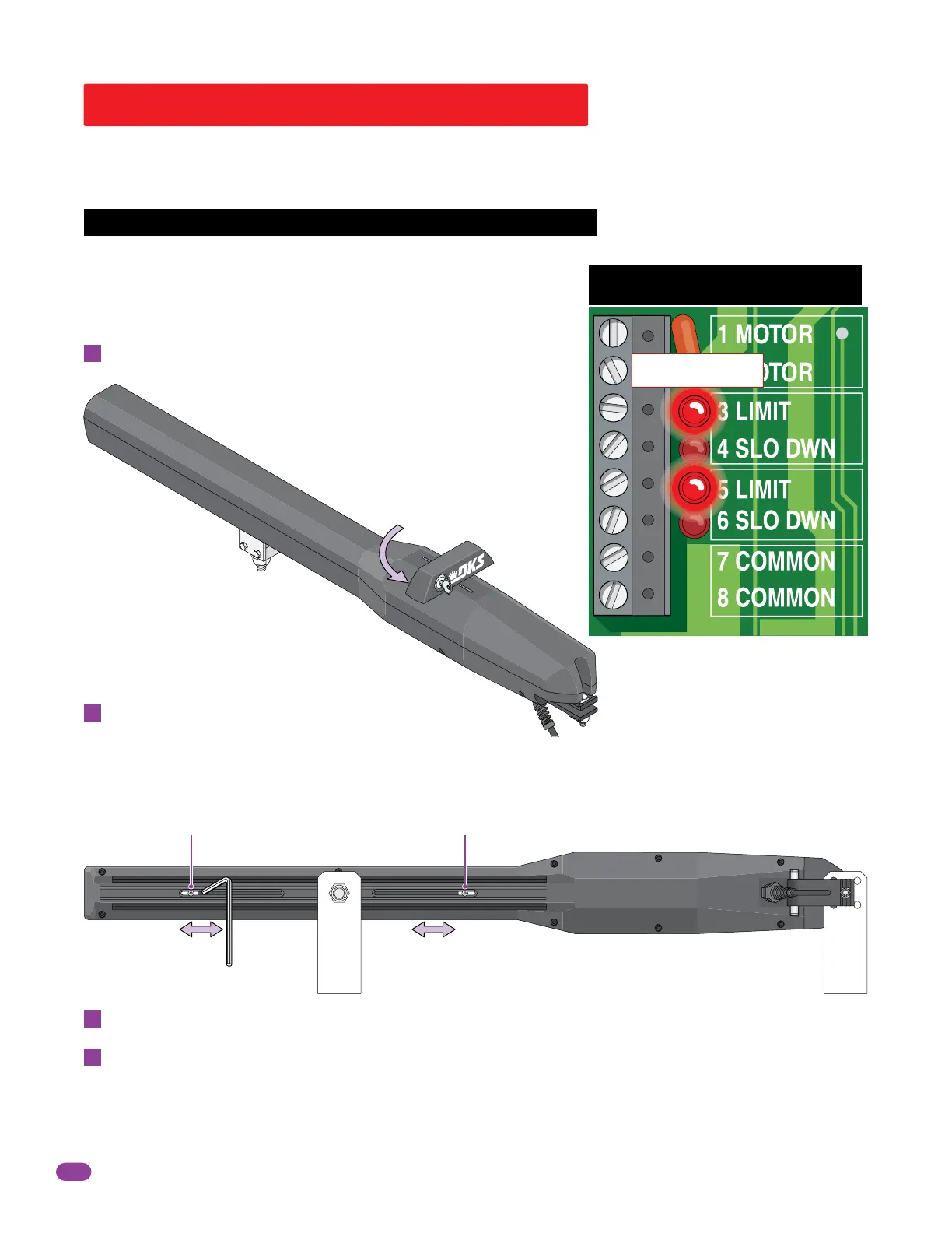
Quick Guide for 6006 Limit Sensors
Manually move the gate to the desired open or closed position.
Loosen set screw and slowly slide the limit assembly.
SLOW DOWN LED will light first, continue sliding until the corresponding
LIMIT LED on the circuit board lights up. Tighten screw.
Manually move the gate to other position. Repeat process with the other
limit assembly.
Manually unlock handle with key and rotate it 90°.
A
B
C
D
Power to the circuit board must be ON when adjusting the limit sensors.
Limit LEDs
Adjust the secondary actuator limit sensors if dual actuators have been installed. DIP-switch SW 1, switch 2 controls
secondary actuator opening direction. DIP-switch SW 1, switch 7 MUST be ON when using dual actuators.
Rotate handle back 90° and re-lock it. Test the gate stopping positions. Re-adjust if necessary.
Note: 3 and 5 limit LEDs can be Open or
Close limits depending on DIP-switch
SW 1, switch 1 and 2 settings.
IMPORTANT: The operator MUST OPEN GATE upon initial power up and OPEN command.
If the operator closes gate after giving first open command, shut off power and reverse DIP-switch SW1, switch 1 setting
otherwise operator will NOT function correctly.
Handle
90°
Set Screw
Hex Wrench
Bottom View
Set Screw
5 LIMIT 3 LIMIT
Note: If factory wired jumpers are on
operator terminals, they MUST be removed.