Vehicle System Specification 5
Specification
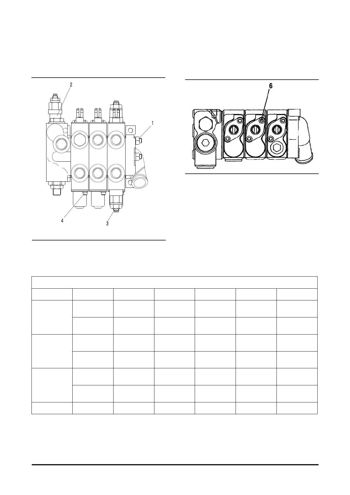
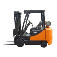
Hydraulic Control Valve
(1) Torque for bolts that hold control valve sections
together ..................... 40 ± 3 N·m (360±24 lb·in)
(2) Adjust main system relief valve pressure for lift
and tilt as shown above. See “Relief valve
pressure check” in Testing &Adjusting.
(3) Adjust auxiliary relief value pressure for the
attachment as shown above. See “Relief valve
pressure check” in Testing &Adjusting.
(4) Torque for screws ..........6 ± 2 N·m (53±20 lb·in)
CONTROL VALVE
ITEM psi kPa bar Kgf/㎠
EU
USA
LIFT
TILT
(2,630±35) 18,100±250
(181±2.5) (185±2.5)
2.0t
NON - EU
NON - USA
LIFT
TILT
(3,130±35) 21,550±250
(216±2.5) (220±2.5)
EU
USA
LIFT
TILT
(2,840±35) 19,500±250
(195±2.5) (199±2.5)
2.5t
NON - EU
NON - USA
LIFT
TILT
(3,130±35) 21,550±250
(216±2.5) (220±2.5)
EU
USA
LIFT
TILT
(3,130±35) 21,550±250
(216±2.5) (220±2.5)
3.0t
NON - EU
NON - USA
LIFT
TILT
(3,130±35) 21,550±250
(216±2.5) (220±2.5)
ALL ALL Aux (2,040±35) 14,000±250
(140±2.5) (143±2.5)