ENGINE DISASSEMBLY
- 70 -
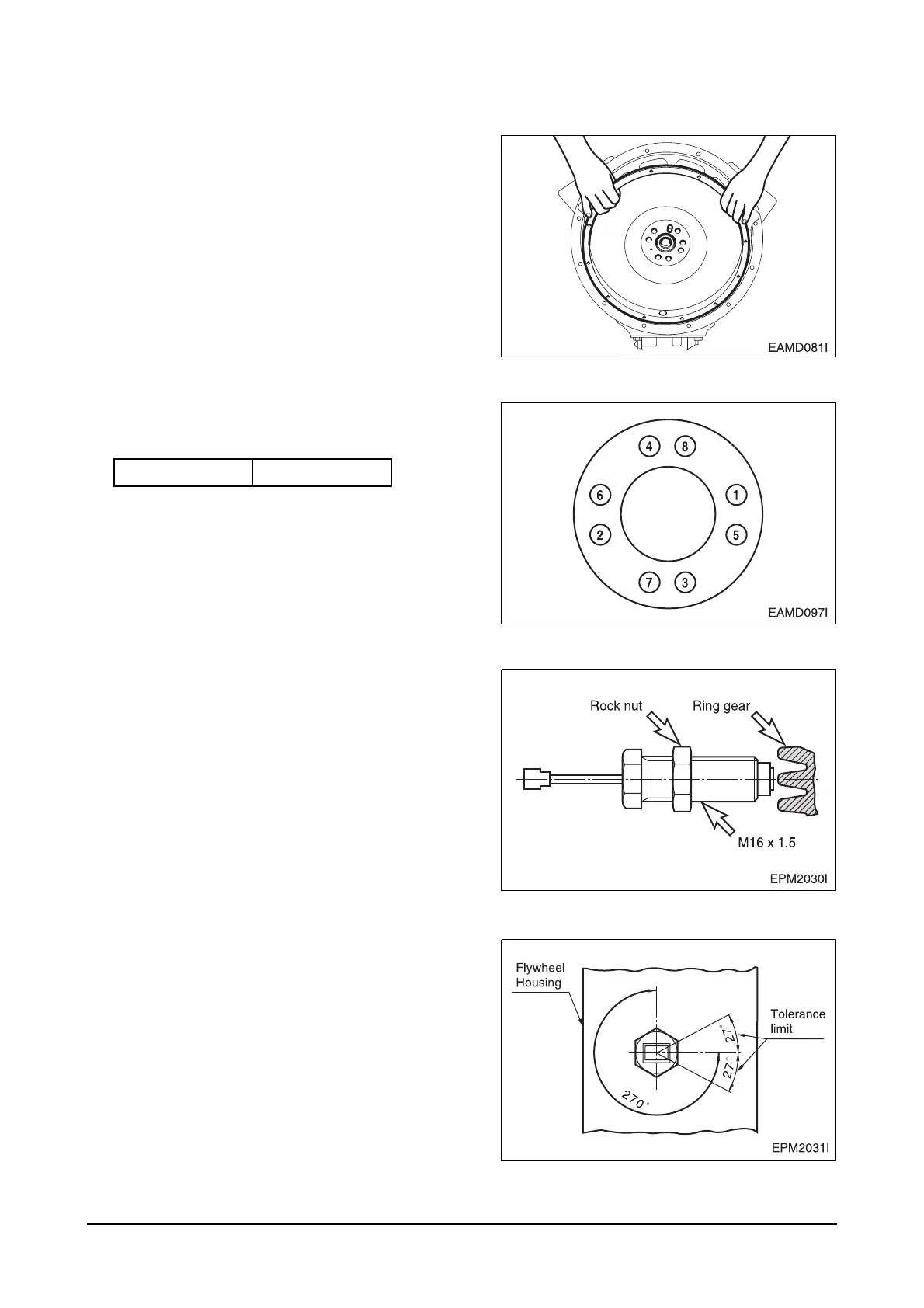
3.3.8. Flywheel
z
Install a guide bar into a bolt hole on the crank
shaft, and lift the flywheel to align the dowel pin
with the pin hole on the flywheel for temporary
assembly operation.
Install bolts in the remaining holes, take out the
guide bar, then install a bolt in the hole where
the guide bar had been inserted.
>
z
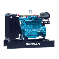
Tighten the fixing bolts using a torque wrench in
a diagonal sequence to specified torque.
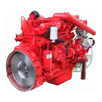
3.3.9. Gear system
z
Move the lock nut to hexagonal side of sensor
completely.
z
Rotate (Clcokwise) the pick-up sensor on
flywheel housing, until the end of it reach on fly
wheel ring gear.
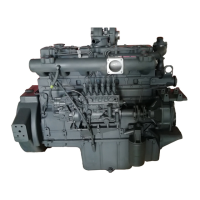
z
Then rotate (Counter clockwise) the pick-up
sensor for 270° (gap 1.0 mm) and fix lock nut.
z
Tolerance limit is 27° (gap
±
0.1 mm)
Torque
18 kgf
•
m