DL06K Interim Tire-4 Diesel Engine Disassembly and Reassembly of Major Components
89
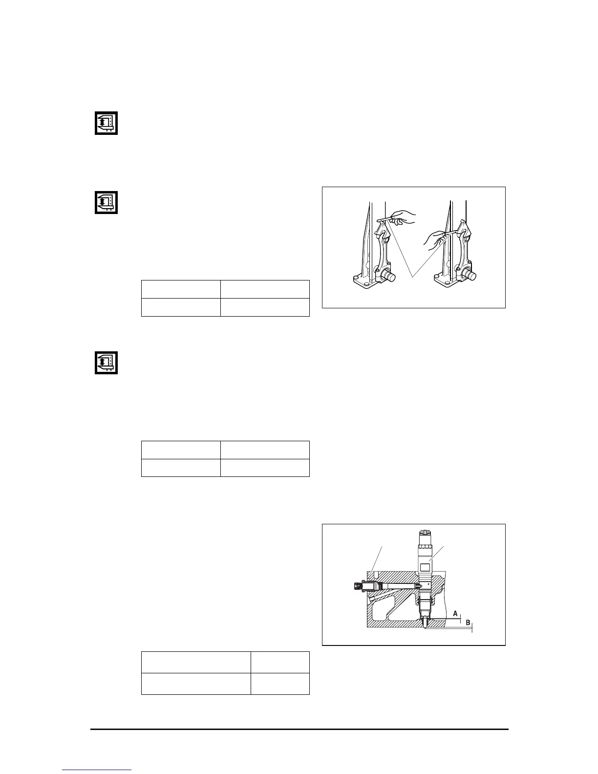
4) Connecting rod inspection
a) Distortion
z Check the connecting rod for distortion. As shown in the figure below, install the
connecting rod to the connecting rod tester, and check for distortion using a
feeler gauge.
z If the connecting rod is found distorted, never re-use it but replace with a new one.
b) Holes alignment (parallelism)
z Measure the alignment of the
connecting rod piston pin bushing holes
with connecting rod big end holes.
z At this time also, use both connecting
rod tester and feeler gauge.
(mm)
c) Wear
z Assemble the connecting rod to the crankshaft and measure connecting rod big
end side clearance using a feeler gauge.
z Assemble the connecting rod to the piston and measure connecting rod small
end side clearance.
z If the measured values are beyond the limit, replace the connecting rod.
(mm)
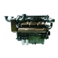
3.2.8. Injector projection
z Insert a seal ring on the cylinder head
and assemble the injector. (Refer to
3.3 chapter for assembly order)
z Measure the clearance between the
cylinder head bottom and injector tip.
If the measured valves are beyond
the limit, replace the seal ring.
(mm)
Standard Limit
0.02 Under 0.1
Standard Limit
0.17 ~ 0.30 0.50
A
(Thickness of seal ring)
2.0
B
(Projection of nozzle)
3.0
EA0M4034
Feeler
gauge
EE1OM075
Cylinder head
Injector