Do you have a question about the Doosan HM 1000 and is the answer not in the manual?
Emergency Stop button pressed or axis limit switch tripped. Check buttons and wiring.
Circuit protector tripped. Check cause, reset or replace protector if necessary.
Hydraulic pump motor overload. Check circuit breaker settings or motor/cable.
Hydraulic pressure below setting. Adjust pressure valve or check pressure switch.
Spindle gear check switch fault. Check switch operation and component parts.
Power phase error detector fault. Check phase connection, reverse phases if necessary.
Power supply module problem. Check contactor KM11 and auxiliary contact A.
Keep Relay settings incorrect or multiple set. Check and select correct machine model settings.
Machine reference point not restored after power on. Restore reference point manually.
Feed hold switch error during AUTO mode. Release feed hold switch or check for short circuit.
Air pressure below specification. Increase factory air pressure or check switch/wiring.
Excessive current in coolant/lubricant pump. Check motor, cable, or circuit breaker.
Error in external coolant unit. Check coolant pressure, filter, or pressure switch.
Operator side door is open. Close door and check safety switch/wiring.
Spindle failed to reach instructed revolutions within 20s. Check parameters or spindle drive.
Spindle rotation command given when prohibited. Instruct S-Code before rotation command.
Spindle orientation command incomplete within 15s. Check parameters or position coder/cable.
Gear shifting not complete within 40s. Check solenoid valve, switches, or hydraulic cylinder.
Tool magazine/ATC pot not initialized when T-code called. Check switch and adjust distance.
Tool change (M06) instructed outside home position. Call tool before M06 or check switches.
Inappropriate T-code instructed. Check tool data and correct number of tool pots.
Tool change (M06) not completed within 6s. Move changer arm to home and resolve cause.
Servo motor inverter for tool magazine tripped. Refer to servo manual for troubleshooting.
ATC door is open. Check door closing signal and detecting switch/wiring.
Splash guard door is open. Check closing signal and detecting switch/wiring.
M60/M61/M62 command not complete within 250s. Check detection switch, valve, wiring.
APC not in initial state when pallet change commanded. Check APC initial condition switches.
Z-axis interlock switch on ATC tripped. Check proximity switch and wiring.
Error in unload checking switch after pallet change. Check APC1/2 positions and switches.
Invalid B-axis coordinate instruction. Correct non-integer number or character.
High-pressure coolant unit (TSC) filter clogged. Replace filter or check sensor/wiring.
B-axis activated in Machine Lock state. Turn off/on power, reset reference points.
Lubricant tank is empty. Refill lubricant or check level switch and wiring.
Lubricant pressure not reaching specified level. Check supply line, distributor valve, or tank.
Parts count reached limit. Adjust or reset parts count settings.
Error in oil cooling unit. Refer to manual for diagnosis and action.
TSC filter clogged, needs replacement. Replace filter or check sensor/wiring.
High-pressure coolant unit (TSC) has insufficient coolant. Check pump, filter, sensor, wiring.
Coolant pressure alarm from TSC unit. Refill coolant or check pump/sensor/wiring.
Tool reached life cycle limit. Take action per Tool Life Management instructions.
NC Reset during auto op, then cycle start. Reset in Edit mode, locate program, then cycle start.
Tool length sensor position incorrect during Pallet Change or Jog mode. Position sensor correctly.
Tool pot sensor switch tripped during tool change/search. Check empty pot, sensor, wiring.
Hydraulic unit oil temp high/low. Check heater, thermometer, wiring.
Problem with coolant chiller unit. Refer to manual for diagnosis and action.
Splash guard door-close check safety switch opened. Turn release key off or check switch/wiring.
Axis interlock tripped, disabling Handle/Jog mode. Check axis positions and switches.
Operator/splash guard door not open before Tool Unclamp. Open door first, check switch/wiring.
Screw conveyor motor error. Check wiring, magnet, insulation, or overload settings.
Error in chip conveyor. Check brake, motor, rotation signal, chain, or switch.
Auto Power Off toggle switch turned on. Turn toggle switch off to deactivate.
Machine Lock Key switch on. Check key switch, wiring, and return axes to reference point.
Screw conveyor set to REV (CCW). Set manual switch to AUTO or FOR (CW).
Feedrate Override switch set to 0%. Change switch to other than 0% or check switch/wiring.
Touch sensor battery depleted. Replace battery or check case/wiring/connector.
Error in touch sensor interface. Check probe, interface, wiring, connector.
Machine entered interference zone. Rotate axis to remove, check PMC G data array.
Machine in Operator Door Interlock Bypass for repair. Instruct M251 in MDI, press NC Reset.
Tool length sensor command incomplete or machine not equipped. Adjust sensor, check wiring, or verify K0.7.
Z-axis reference point not set when X/Y attempted. Restore Z-axis reference point first.
5th axis clamp/unclamp incomplete or timed out. Adjust pressure switch or check wiring.
M23 not instructed at start of program in PMG mode. Instruct M23 at program beginning.
B-axis moved while X-axis not centered (K8.6=1). Move X-axis to center, then move B-axis.
Spindle gear check switches not detected. Check gear box switches on DGN screen.
ATC disabled (K7.6=1) but tool change/call commanded. Set K7.6 to 0, then instruct.
Waiting pot/spindle tool data zero when tool change commanded. Call tool, ensure pot empty, enter actual tool number.
ATC door command incomplete or not closed. Instruct door open/close alternately, check switch/wiring.
ATC operation activated during T-code call or M06. Instruct command only when current operation is complete.
ATC magazine manual mode, main OP set to AUTO. Set touch panel mode switch to AUTO.
Tool call/change incomplete within 45s. See sequence chart or alarm table for problem solving.
Error detecting ATC changer initial position. Check stop position and proximity switch/dog/wiring.
Left/right position sensor signal mismatch. Adjust proximity switch, check wiring.
180 CW/CCW position sensor signal mismatch. Adjust proximity switch, check wiring.
Waiting pot backward/forward proximity signal mismatch. Adjust switch, check wiring.
Tool detection switch for waiting pot tripped. Instruct T-code to call tools, check switch/wiring.
Pin locking/unlocking proximity signal mismatch. Adjust switch, check wiring.
Spindle tool number identical to waiting pot. Check tool numbers, assign unique numbers.
Tool magazine rotation incomplete within 230s. Check waiting pot tool count, sensor, wiring.
Tool magazine door open. Close door, check safety switch, wiring.
Servo drive battery alarm. Replace battery or refer to servo drive manual.
APC not in initial state. Check splash guard/pallet changer arm switches and wiring.
Beam sensor tripped entering APC. Exit APC, press Reset/Set-Up, check sensor/wiring.
Pallet/table clamp/unclamp signal mismatch. Adjust position switch or check wiring.
Pallet or table not clamped. Adjust position switch or check wiring.
Set-Up switch not pressed after workpiece placement. Press Set-Up switch or check switch/wiring.
APC manual OP mode switch set to Manual. Set touch panel mode to AUTO.
APC Changer Arm 1/2 Adv/Ret signal mismatch. Adjust switch, check wiring.
Splash guard door open/close signal mismatch. Adjust switch, check wiring.
| Brand | Doosan |
|---|---|
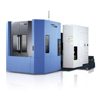
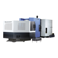
| Model | HM 1000 |
| Category | Industrial Equipment |
| Language | English |