30 MAINTENANCE
7/20, P65
The retaining clamp should be kept tight enough to prevent the battery
from moving.
PRESSURE SYSTEM
At 500 hour intervals it is necessary to inspect the external surfaces of
the system (from the airend through to the discharge valve(s))
including hoses, tubes, tube fittings and the separator tank, for visible
signs of impact damage, excessive corrosion, abrasion, tightness and
chafing. Any suspect parts should be replaced before the machine is
put back into service.
TYRES/TYRE PRESSURE
See the GENERAL INFORMATION section of this manual.
RUNNING GEAR/WHEELS
Check the wheel nut torque 20 miles (30 kilometres) after refitting the
wheels. Refer to the TORQUE SETTING TABLE later in this section.
Lifting jacks should only be used under the axle.
The bolts securing the running gear to the chassis should be checked
periodically for tightness (refer to the MAINTENANCE SHEDULE for
frequency) and re-tightened where necessary. Refer to the TORQUE
SETTING TABLE later in this section.
BRAKES
Check and adjust the brake linkage at 500 miles (850Km) then every
3000 miles (5000Km) or 3 months (whichever is the sooner) to
compensate for any stretch of the adjustable cables. Check and adjust
the wheel brakes to compensate for wear.
Adjusting the overrun braking system (KNOTT
Running Gear)
1. Preparation
Jack up the machine
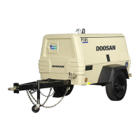
Disengage the handbrake lever [1].
Fully extend the draw bar [2] on the overrun braking system.
Requirements:
During the adjustment procedure always start with the wheel brakes.
Always rotate the wheel in the direction of forward movement.
Ensure that an M10 safety screw is fitted to the handbrake pivot.
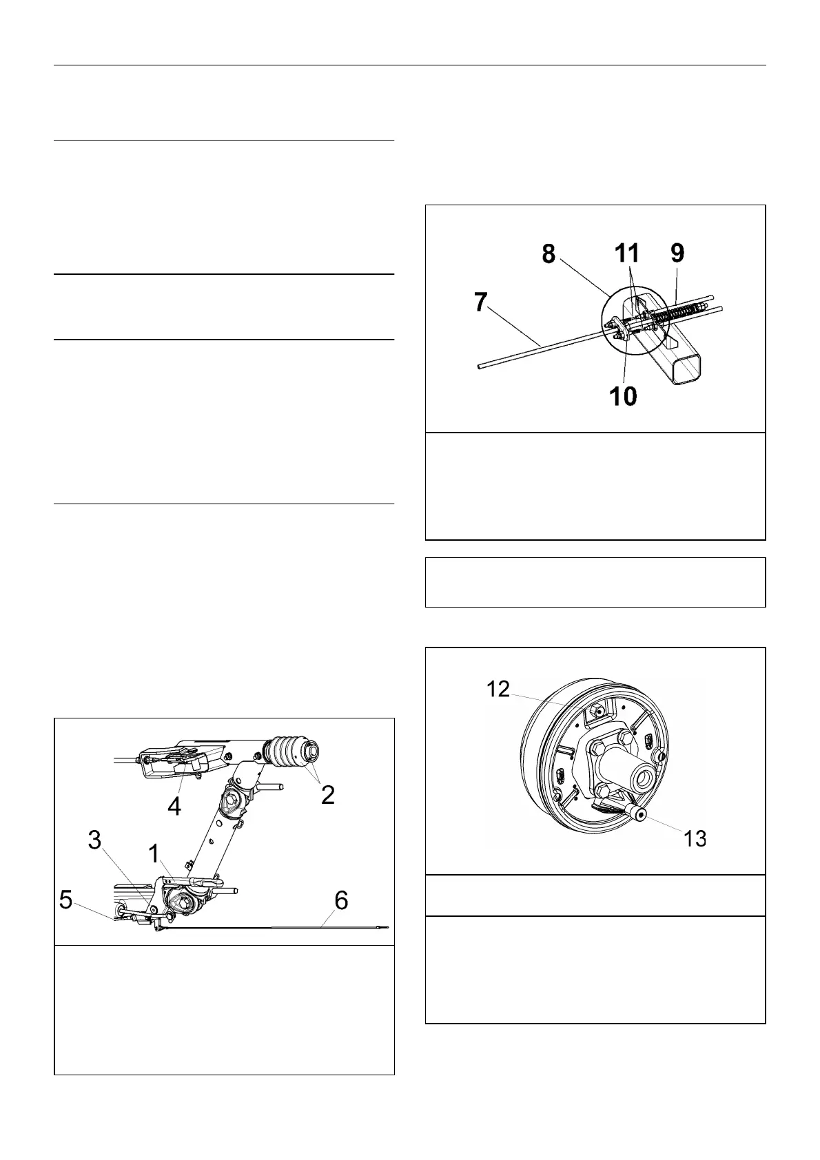
The brake actuators must not be pre-tensioned - if necessary loosen
the brake linkage [7] on the brake equalisation assembly [8].
Check that brake actuators and cables [11] operate smoothly.
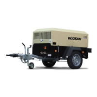
2. Brake Shoe Adjustment
Tighten adjusting screw [12] clockwise until the wheel locks.
Loosen adjusting screw [12] anti-clockwise (approx. ½ turn) until the
wheel can be moved freely.
1. Handbrake lever
2. Draw bar and bellows
3. Handbrake lever pivot
4. Transmission lever
5. Brake cable
6. Breakaway Cable
7. Brake linkage
8. Equalisation assembly
9. Compression spring
10.Equaliser plate
11.Cable
CAUTION: The compression spring [9] must only be lightly pre-
tensioned and when operating must never touch the axle tube.
Never adjust the brakes at the brake linkage [7].
12.Adjusting screw
13.Cable entry
Width across flats of adjusting screw [12]
Brake size Key width
160x35 / 200x50 SW 17
250x40 SW 19
300x60 SW 22