RST
DORMA
18K
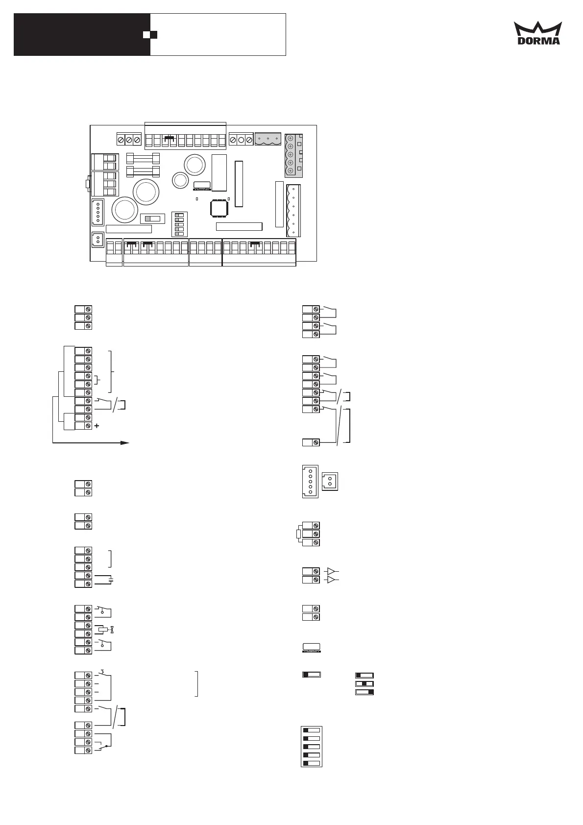
Connection blocks Control board B
Technical data
Power supply: 230 VAC ±10%, 50/60 Hz
Fuse F2: T 1,6 A at 24 VAC
Fuse F3: T 1,6 A at 12 VAC
LED: Error indicator Steuerung A
LED: Error indicator Steuerung B
A (V20)
B (V18)
Night-bank activator
Internal activator
External activator
Safety sensor, opposite hinge-side
Safety sensor hinge-side active leaf;
jumper if not used
Safety sensor hinge-side inactive leaf
Jumper if not used
5 + 2-pin interface block for connection cable
linking two control modules for coordinated
double-leaf operation
Control module B (master/ active leaf)
Controls module A (Slave/ inactive leaf).
Stabelized power supply for smoke detector
(max. 100mA) - not switched off by drive unit
disabling contact at terminal 5/6 limit switch
cut off input
Sensoric output test GF
Mode selector:
Single-leaf mode
Double-leaf mode
Motor lock mode
Sensoric output test SF
Hold open time 0 - 30 sec.
Presence sensor on opposite hinge side of
passive leaf
DIP Schalter Grundeinstellung alle “OFF”
OFF ON
1 Test high active test low active
2 Inactive test GF BS Active test GF BS
3 Inactive test GF BGS Active test GF BGS
4 Inactive test SF BS Active test SF BS
5 Inactive test SF BGS Active test SF BGS
Secondary side, transformer
Power supply to external loads,
e.g. electro-mechanical lock (radar
detector) 1+2 = 24 VAC, 2+4 = 12 VAC.
Drive unit disabling contact for e.g.
smoke detector input; jumper if not used
Power supply to external loads,
e.g. electro-mechanical lock (max 700mA).
max. 1400 mA
Primary side, transformer
Incoming power supply:
230 VAC ±10%, 50/60 Hz
Motor
Capacitor
„Door open“ limit switch
Solenoid valve
„Door closed“ limit switch(cam) Switches off
the hinge-side safety sensor (e.g.IRS)
OFF (GND)
Exit only
Permanent open
Automatic
„Door closed“ limit switch (switches off the
safety sensor on the opposite hinge-side
jumper if not used.)
Electro-mechanical lock:
Floating contact (change over contact),
fixed pulse duration of 1 sec.1 sec.
Programme switch
50
15
52
54
53
55
51
14
X9
4
1
1
4
2
2
5
6
34
35
31
32
33
36
37
X1
X2
X3
24 V
12 V
0V
GND
24 VDC
N
L1
U
V
W
C
NO
NC
6µF
39
38
40
41
42
43
44
16
17
18
19
20
21
12
48
11
8
13
7
46
45
49
47
27
26
25
X4
X5
X6
X7
X8
56
57
X11
R26
S1
A
B
C
58
59
60
X13
61
62
X15
S2
OFF ON
X10
X14
X2
X1
F2
F3
X7
R26
X8
S2
ABC
X9
X10
X11
35
333231
57
56
34652244 11
37 36 39 38
44
43
42
41
40
21
20
19
18
17
16
1245111346472726254849875051525315145455
X3 X4
L1 N
X5
X6
B
N
V
U
58
59
60
X13
6162
X14
S1
X15
18K
A
B
34
6. Terminal diagram control unit B