45
ED100/ED250 08-2018DL4614-100
dormakaba ED100/ED250 OHC Installation Instructions Chapter 17
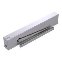
1 PCB holder
assembly, Terminal
PCB DC4630
2 Low voltage
terminal PCB
2.1 Ribbon cable
connector
3 1/4-20 x 1/2"
SBHCS
4 1/4" square nut,
installed in header
track
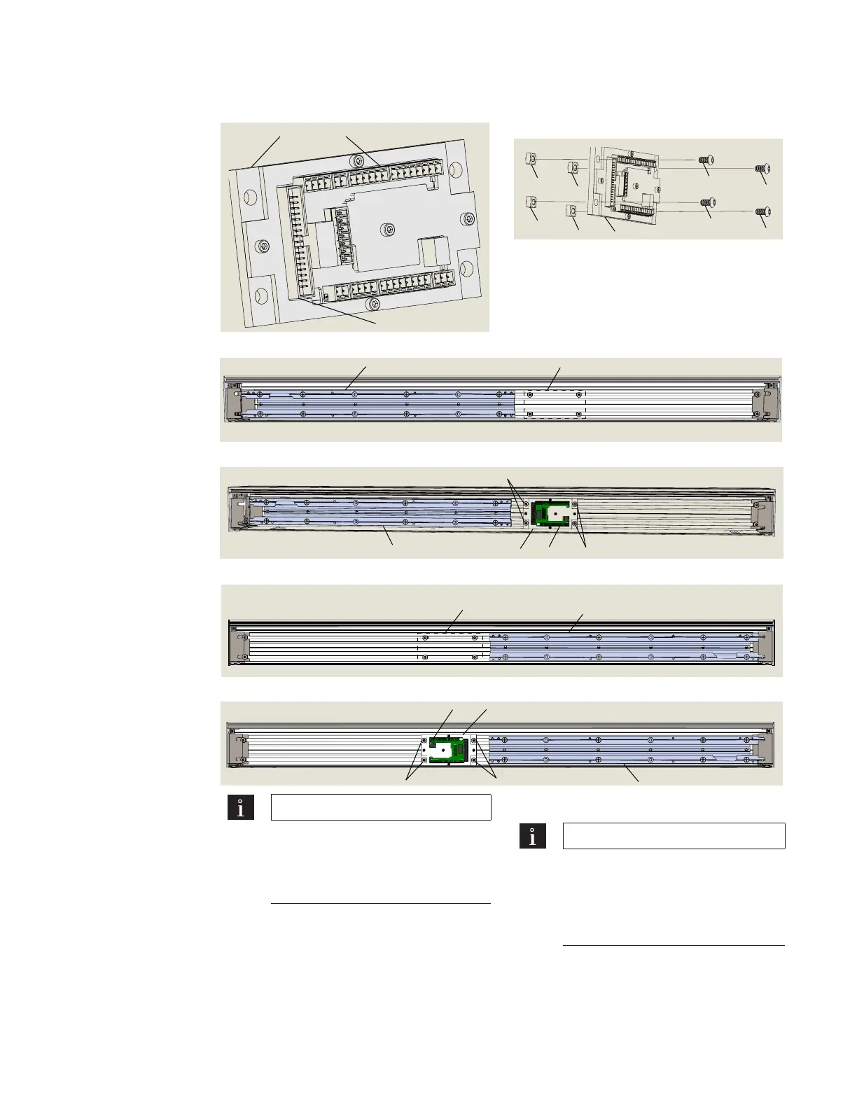
. Install low voltage terminal PC board module
Fig. 17.4.1 Terminal PC board module
1
2
2.1
Fig. 17.4.6 Terminal PC board module
fasteners
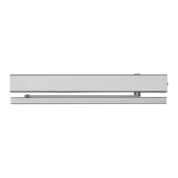
Fig. 17.4.3 Terminal PC board module installed in header; ED100/ED250 operator on left
3
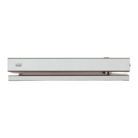
Fig. 17.4.5 Terminal PC board module installed in header; ED100/ED250 operator on right
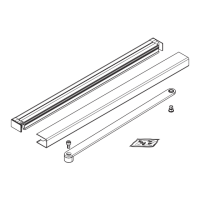
Fig. 17.4.4 Fasteners for Terminal PC board module; ED100/ED250 operator on right
1 PCB holder
assembly, Terminal
PCB DC4630
2 Low voltage
terminal PCB
3 1/4-20 x 1/2" SBHCS
4 1/4" square nut,
installed in header
track
5 OHC mounting
plate installed on
left
Fig. 17.4.2 Fasteners for Terminal PC board module; ED100/ED250 operator on left
1 PCB holder
assembly, Terminal
PCB DC4630
2 Low voltage
terminal PCB
3 1/4-20 x 1/2" SBHCS
4 1/4" square nut,
installed in header
track
6 OHC mounting
plate installed on
right
TIPS AND RECOMMENDATIONS
Ribbon cable from ED/ED
OHC operator connects to
connector on Terminal PC board
(Fig. ..).
.. Install Terminal PC board module.
TIPS AND RECOMMENDATIONS
Refer to Figures .. through
.. for module installation for
ED/ED OHC operator
located on right or left side of
header.
. Install module in header using fasteners
(,) installed in header tracks. Do not
over-tighten SBHCS's.
. Position module in header track as
shown in Fig. .. or ...
5
4 sets 3,4
6
4 sets 3,4
1
2
5
3
3
 Loading...