6 Saflok Quantum Pixel PK3693_T 02-19
Lock trim installation (continued)
2. Controller Assembly Installation
a. Lift controller to top of pocket and center horizontally to mark pilot hole locations based on case
mounting holes
b. Pre-Drill #12 screw pilot holes, ensure holes are centered for proper face plate alignment
c. Slide tray out partially from controller to ensure tabs are not bent when securing #12 screws
d. Lift and center assembly to ensure proper alignment
e. Secure with included #12 pan head screws
f. Slide the tray out partway to and ensure all connections are secure
*Do not connect the battery at this point
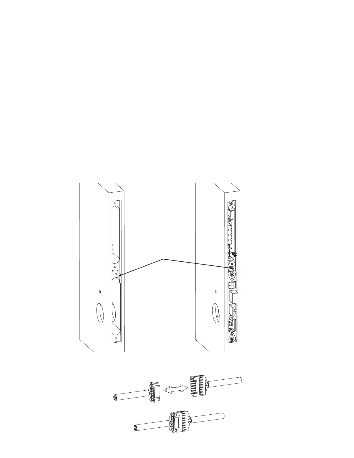
g. Connect the harnesses from the mortise and controller together
*Do not seat the slide tray in door at this point
Figure 6 - Wire Channel in Door Edge
Wire Channel
Figure 7 - Controller and Mortise Harness Connection
 Loading...