EasyManua.ls Logo

Dors 1050 - User Manual

Dors 1050
8 pages
Print Icon
To Next Page IconTo Next Page
Loading...
User Manual
Rev.
1
Int
2018
Production date:
USER MANUAL
MULTIFUNCTIONAL
COUNTERFEIT DETECTOR
1050
Question and Answer IconNeed help?

Do you have a question about the Dors 1050 and is the answer not in the manual?

Summary

Brief Information for Customers

Purpose of the Device

Explains the intended use and functions of the DORS 1050 counterfeit detector for verifying security features.

Device Capabilities

Outlines the specific verification capabilities and technologies integrated into the DORS 1050.

Important Safety Precautions

Crucial safety warnings to prevent injury and device damage during operation and handling.

Delivery Set and Appearance

Delivery Set Contents

Lists the included components that come with the DORS 1050 multifunctional counterfeit detector.

Device Appearance Overview

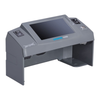
Identifies and describes the external components, controls, and connection ports of the DORS 1050.

Device Preparation and Operation

Preparing for Operation

Ensures the device is correctly set up and ready for use, covering essential pre-operation checks.

Device Operation Modes

Covers the general procedures for using the DORS 1050 during detection processes.

Verification of Magnetic Marks

Details how to verify magnetic marks using the inductive sensor and magnetic bias area.

Verification of UV Marks

Explains how to check for UV security features on banknotes using UV light.

Verification of IR Marks

Describes the process for verifying infrared security features on banknotes.

Verification in White Light

Guides on using white light to inspect banknotes for watermarks and relief printing.

Maintenance and Troubleshooting

Switching Device Off

Procedure for safely powering down the DORS 1050 counterfeit detector.

Care and Maintenance

Instructions on cleaning the device surface and general upkeep.

UV Lamp Replacing Procedure

Step-by-step guide for safely replacing the UV fluorescent lamp in the device.

Troubleshooting Common Issues

Provides solutions for common problems like the device failing to switch on or lights not working.

Technical Specifications and Support

Device Specifications

Lists the technical details, including voltage, power consumption, dimensions, and operating ranges.

Transportation, Storage, and Disposal

Guidelines for safely transporting, storing, and disposing of the counterfeit detector.

Support and Warranty Information

Details on the manufacturer's warranty coverage and terms for the DORS 1050.

Overview

The DORS 1050 is a multifunctional counterfeit detector designed for the visual authenticity verification of banknotes and security printing documents with protective marks. Manufactured by DORS Industries (China) Ltd., this device has a service term of 7 years, provided it is used in strict accordance with the user manual and applied technical standards.

Function Description

The DORS 1050 is equipped with several features to facilitate comprehensive counterfeit detection:

  • Ultraviolet (UV) Source: Consists of a 1 fluorescent lamp (4W) for verifying the absence of general luminescence and the availability of luminescence in specific areas (marks, security threads, and fibers) under UV light.
  • Top Infrared (IR) Source: Emits at a 940 nm wavelength to verify the availability of IR images in reflected light.
  • Magnetic Sensor (MG): Detects zones printed with magnetic ink. When magnetic ink is detected, an LED flashes green. For worn-out banknotes, placing them on the magnetic bias area for several seconds can improve detection quality.
  • White Light Source: Allows for inspection of banknote surfaces and other documents with protective elements in white oblique reflected light, such as relief printed elements. It also helps verify watermarks and security threads on paper. A point-type LED of high brightness is used for white illumination, so direct viewing of the light source is not recommended.
  • 4.3" (10.9 cm) TFT Display: Transmits the image of the banknote or document placed in the viewing zone, allowing for detailed examination.
  • Video Camera: Captures the image of the document for display on the monitor.

The device helps users:

  • Verify the availability of IR images in reflected light.
  • Verify the absence of general luminescence in ultraviolet rays.
  • Verify the availability of luminescence of specific areas of a sheet in ultraviolet rays (marks, security threads, and fibers).
  • Inspect the surface of banknotes and other documents with protective elements in white oblique reflected light (e.g., verify availability of relief printed elements).
  • Verify the availability of watermarks and security threads on paper.
  • Verify the availability of zones printed by magnetic ink.
  • Examine the image of a banknote or other document on the 4.3" TFT display.

Important Technical Specifications

  • Supply Voltage: 190-240 V~50/60 Hz
  • Current Consumption: 0.08-0.06 A
  • Power Consumption (not more than): 14 W
  • Weight (not more than): 0.48 kg
  • Overall Dimensions (Width x Depth x Height): 200x87x119 mm
  • Power of UV Source: 1 x 4 W
  • Peak Wavelength of UV-radiation: 365 nm
  • Operating Range of IR Source: 800-1000 nm
  • Operating Temperature: +5 to +40°C

Usage Features

Preparing for Operation:

Before operation, ensure the device's body and UV lamp are intact. Do not connect the product to the power supply if it has a damaged body, a damaged UV lamp, or no UV lamp. For optimal viewing, position the device so the operator's gaze is perpendicular to the screen surface. Connect the AC adapter to the device's power jack and plug it into a 190-240V, 50-60 Hz power supply. Switch on the device using the power switch (item 1, Fig. 1). The screen will turn on, indicating the device is ready.

Operation Modes:

Once switched on, the device screen (item 2, Fig. 1) activates, and either UV or white light mode is enabled, depending on the position of the switch (item 4, Fig. 1). This switch allows changing the light mode during operation. In both modes, the IR image of the banknote placed in the viewing zone (item B, Fig. 1) is displayed on the monitor.

Verification of UV Marks:

Place a banknote or document in the viewing zone (item B, Fig. 1). Turn the key (item 4, Fig. 1) to position 1 to activate UV mode. Examine UV images on the surface of the banknote/document. Simultaneous UV and IR verification is possible, with the IR image visible on the screen (item 2, Fig. 1). It is prohibited to look at the UV lamp when the device is working.

Verification of IR Marks:

Place a banknote or document in the viewing zone (item B, Fig. 1). IR verification is activated automatically when the device is switched on. Observe the IR images on the screen (item 2, Fig. 1).

Verification in White Light:

Place a banknote or document in the viewing zone (item B, Fig. 1). Turn the key (item 4, Fig. 1) to position 2 to activate white light mode. This mode is ideal for observing the relief of printed elements visible in oblique white light and for verifying watermarks.

Safety Precautions:

  • UV Lamp: It is prohibited to look at the UV-lamp during device operation.
  • Electrical Safety: It is prohibited to touch the device and the power cord plug with wet hands, as this may result in an electric shock. When unplugging, hold the plug, not the cord, to avoid damage. Move the device only after the power cord plug has been disconnected.
  • Installation: Do not install the device with its UV-lamp visible to the operator. Install the device on an even horizontal surface, avoiding direct sunlight and spot artificial illumination.
  • Cold Conditions: If the device has been under cold conditions for a long time, keep it at room temperature for at least two hours before switching it on.

Maintenance Features

Switching Device Off:

Press the power switch key (item 1, Fig. 1) to turn off the screen. Users can decide whether to disconnect the power cord. For long-term storage (more than several days) or moving the device, disconnect the power plug from the socket.

Care and Maintenance:

  • Cleaning: To clean the device surface, use water-based neutral detergents (e.g., dishwashing liquid) or isopropyl alcohol-based cleaning compositions. Carefully remove any excess detergent or cleaning solution.
  • Safety During Cleaning: Before cleaning, ensure the power plug has been removed from the power socket. Avoid detergent or cleaning composition entering the device. Use only a soft tissue to apply cleaning agents; do not use brushes, sprayers, or aerosol sprays.
  • UV Lamp Replacement: The fluorescent lamp is a consumable item and not covered by the manufacturer's warranty. If a lamp fails, it should be replaced with a DORS TL 4W/08 F4 T5/BLB lamp. The device can operate for up to 8 working hours with a failed lamp.
  • UV Lamp Replacement Procedure:
    1. WARNING! Before replacing a lamp, ensure the power plug has been disconnected from the power socket.
    2. Turn the device upside down and place it on a soft cloth-covered table.
    3. Gently turn the failed lamp around its axis by a quarter of a turn, holding it with two fingers of each hand.
    4. Remove the failed lamp (item 6) with its protection covers (item 11) from the holders (item 10) (see Fig. 2).
    5. Remove (shift off) the lamp protection covers (item 11).
    6. Inspect the new lamp for scratches, chipping, damage, or contamination. Do not install a lamp with mechanical damages or bulb contamination.
    7. Insert the new lamp into the holders until it stops. Turn it around its axis by a quarter of a turn to fix it.
    8. Place the protective cover (item 11) on each lamp holder (no tool required).
    9. Return the device to its working position and test the UV light to confirm the repair.
    10. Pack the failed lamp and hand it over to a specialized disposal service.
  • Determining a Failed UV Lamp: Use an A4 white paper sheet (not more than 80 g/m2). If the paper fluoresces intensely in the viewing zone (B), the UV lamp is working. If it doesn't fluoresce, the lamp needs replacement.
  • Determining a Failed White Light Source: This is done visually; if the white lamp does not light up when the white light mode is on, it has failed.

Transportation, Storage, and Disposal

  • Transportation: The device should be transported in its standard package by sea, railway, air, or truck. Transportation conditions require temperatures of -20°C to +50°C, relative humidity up to 95% (without water condensation at +25°C), and atmospheric pressure of 84 to 107 kPa.
  • Storage: Store the device in its package in a heated warehouse at temperatures of 0°C to +40°C, with relative air humidity not exceeding 80%.
  • Disposal: The device meets the requirements of the European Union's RoHS Directive. Before disposal, remove the fluorescent lamp following items 1-4 of the "UV-LAMP REPLACEMENT PROCEDURE." The removed lamp must be handed over to a specialized disposal service. The device without the UV lamp can be disposed of as domestic waste.

Support and Warranty

The manufacturer provides a 12-month warranty from the date of purchase. The manufacturer, through its local dealer, is obligated to repair failed devices if the user has adhered to all requirements of this User Manual. Failure of fluorescent lamps is not covered by the warranty. Device damage resulting from improper use, falling, or excessive physical force is also not covered.

Dors 1050 Specifications

General IconGeneral
BrandDors
Model1050
CategorySecurity Sensors
LanguageEnglish

Related product manuals