MACHINE FOR BINDING BANKNOTES AND SECURITIES (BANDING MACHINE) DORS 500
12
* XX numeric value.
MACHINE FOR BINDING BANKNOTES AND SECURITIES (BANDING MACHINE) DORS 500
13
Table 1. Values of the parameters of the presets *
* They may differ depending on the version.
Table 2. Parameters of the "SET" modes
Parameter
Display
rea
ding*
Description
Loop size "L" L XX
Allows setting of the required loop size (full)
within the range of 20…90
Loop size "S" S XX
Allows setting of the required loop (final)
within the range of 5…89
Tightening force
of pack "F"
F XX
Allows setting of the required tightening force
of the pack within the range 1…25
Welding
temperature "t"
t XX
Allows setting of the required welding tempera
ture within the range of 1…10
Time of the pack
retention for reli
able welding "r"
r XX
Allows setting of the required retention time of
the pack within the range of 1…25
Sound indication
"Snd"
_ or o
Allows to switch on and switch off the sound
indication of the beginning and the end of
binding process.
Change of the setting parameters
To change the parameters of the set
ting being used, switch to the "SET" mo
de by pressing the "SELECT" button.
Then there will run the "SEt" caption
and the device will switch to the mode
of changing the parameters of the
settings.
It is impossible to change the parame
ters "L", "S", "F" in the presets (1 to 4),
parameters "t" and "r" can be changed
within the specified limits. It is possible
to change parameters in the user's set
tings; this is indicated on the display by
the flashing of the parameter value.
To change (review) the parameters
values, perform the following actions:
1. Press the "SELECT" button in the
"Hand" or "Auto" modes. The devi
ce switches to the "SET" mode.
2. Press the "SELECT" button to cho
ose the parameter for setting or
reviewing.
3. Use the buttons "+"/"" to select
the required parameter value.
4. To change the other parameters,
repeat step 2; to exit from the
"SET" mode, press the "AUTO"
button.
After the exit from the "SET" mode,
changes of the loop parameters come
into effect at formation of the next
loop. The other parameters come into
effect immediately after the exit from
the setting modes.
The functions of the buttons depend
on the selected operation modes of
the device. Table 3 contains the fun
ctions of the buttons in various modes.
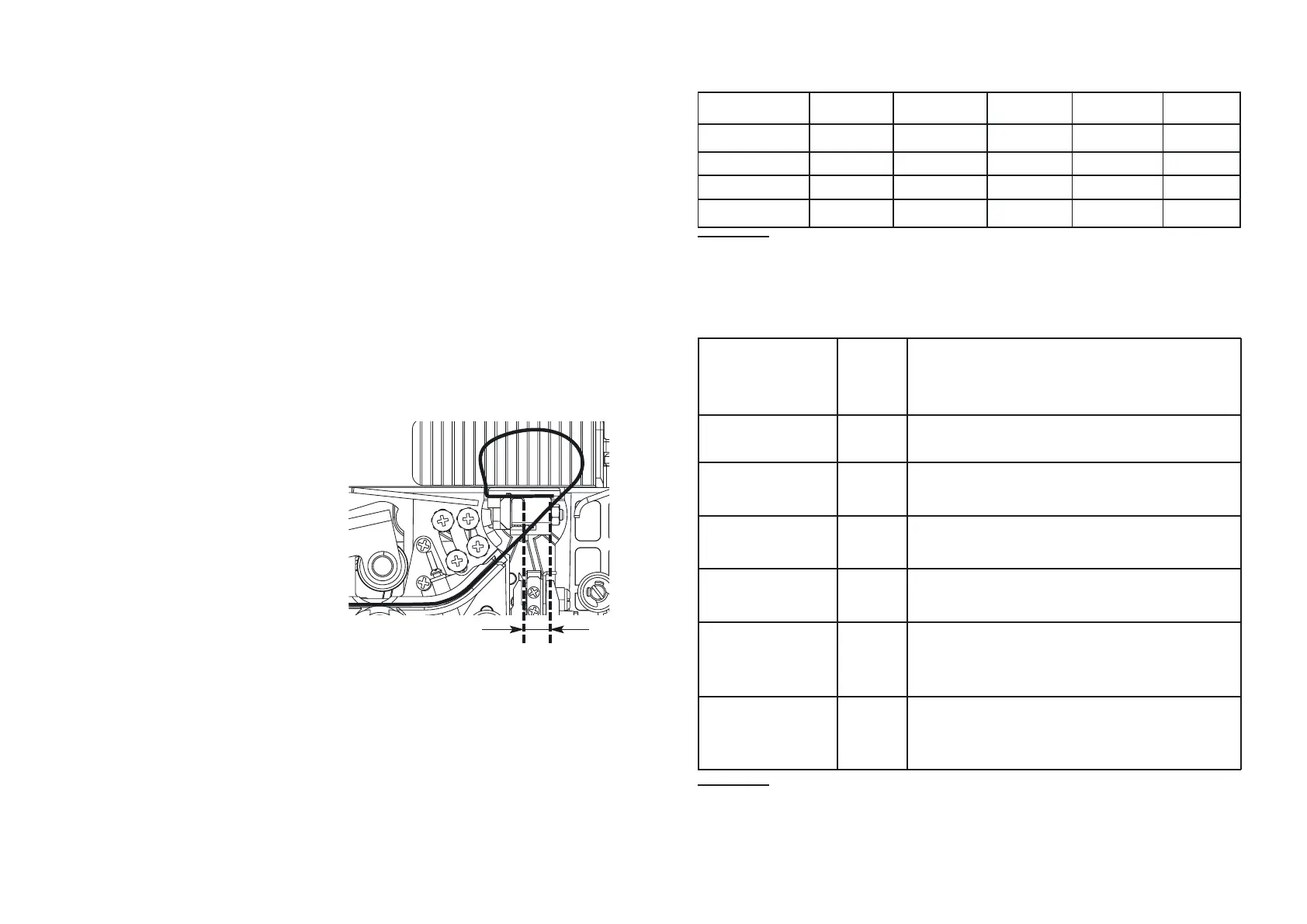
Glue Seam Size Adjustment
In the "AUTO" mode, press "START" +
"START" + "SELECT" simultaneously
to switch to the installed tape size au
tosensing mode (see size C in Figure).
The indicator displays "LXXX" where
XXX is the installed tape size. The fac
tory setting is 416. You may change
this value by pressing the +/ buttons.
The lower the value the thinner the
glue stripe, however, exceeding a cer
tain size may cause the glue stripe irre
gularities.
Recommendations
on the configuration setting
values are:
1. The tension (F) shall be selected
with regard to the quality of the
tape used. High tension values
Mode of fine tuning of the tape size
under the shank
Setting L, cm S, cm F t r
1 40 8 5 4 8
26033548
38040548
4...9 40 8 5 4 8
 Loading...