12 DR
®
SELF-FEEDING CHIPPER
Installing the Tow Bar and Lights for the Road Tow Model
Note: For easier installation, keep the machine on the pallet and supports until the
Tow Bar is installed.
Tools and Supplies Needed:
7/16 Wrench
Two 1/2" Wrenches
Two 3/4" Wrenches
Wire strippers/Cutters
Stiff Wire with Hooked End
Cable Ties (Supplied with machine)
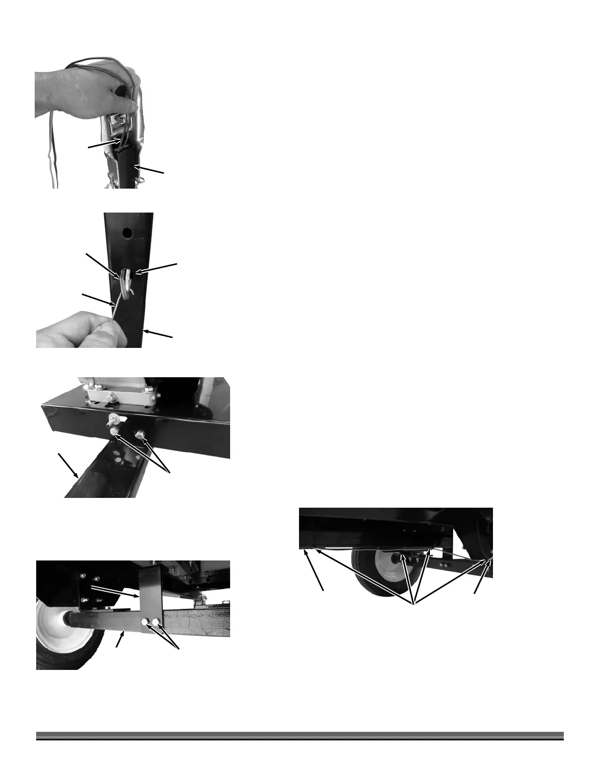
1. Insert the ends of the Yellow/Brown and Green/Brown Wires of the
Wire Harness into the Tongue Assembly and down into the Tow Bar (Figure 7)
until they reach the large hole (Figure 8).
2. Pull the ends of the wires through the large Hole by using a stiff wire
with a small hook formed at the end.
3. Continue pulling the Wires through leaving approximately two feet of
the Plug end extended beyond the front of the Tongue assembly.
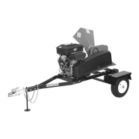
4. Position the Tow Bar under the Base and secure the front Bracket with
3/8-16 x 1" Bolts and Locknuts using two 9/16" Wrenches (Figure 9).
5. Secure the rear of the Tow Bar to the Axle with 3/8-16 x 1" Bolts and
Locknuts using two 9/16" Wrenches (Figure 10).
6. Position the Yellow/Brown Wires along the left side of the axle and up
to the light location over the Fender (Figure 11).
7. Position the Green/Brown Wire along the right side of the axle and up
to the Light location over the Fender.
8. Secure the Wires under the Frame with Cable Ties at the four places
shown.
Figure 11
Cable Ties
Yellow/
Brown
Wire
Wires
Bolt and
Locknut
Figure 10
Tow Bar
Rear Bracket
Road Tow
xle
Bolt and
Locknut
Figure 9
Tow Bar
Base
Wires
Figure 8
Tow Bar
Hook Tool
Larger Hole
Figure 7
Wires
Tow Bar
 Loading...