CONTACT US AT www.DRpower.com 13
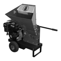
Attaching the Discharge Chute
Tools Needed:
• Two 1/2" Wrenches
Note: You may need to loosen surrounding hardware near the Discharge Chute
mounting holes to make it easier to insert the Discharge Chute between the
Housing Plates (Figure 9). Tighten all hardware when finished.
1. Position the Discharge Chute facing away from the Hopper as shown and
secure with two 4-1/2" long 5/16-18 Bolts and Locknuts.
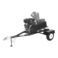
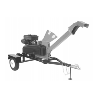
Installing the Wiring for the Road Tow Model
Tools and Supplies Needed:
• Two 3/4" Wrenches
• Wire strippers/Cutters
• Electrical Tape (or equivalent)
• Cable Ties (Supplied with machine)
1. Remove the Tow Hitch Bolts and Locknuts (Figure 10). Remove the Tow
Hitch.
2. Unwrap the Wiring Harness and locate the two colored wire ends that do
not have connectors on them (Figure 11). Note: The white wire will not be
used in this step.
3. Tape the ends of the wires together and also tape them together
approximately 6" from the end.
4. Insert the taped end of the wires into the Tow Bar and push the wires over
the Chain Bolt (Figure 12). Continue pushing the wires until they reach the
large hole at the center of the Tow Bar (Figure 13).
5. Pull the ends of the wires through the large Hole using a stiff wire with a
small hook formed at the end.
6. Continue pulling the Wires through leaving approximately three feet of the
Plug end extended beyond the front of the Tow Bar (Figure 12). Note: You
will want enough extra wire to plug into the tow vehicle and allow turning
without binding.
7. Position the Yellow/Brown Wires along the left side of the axle and up to
the light location over the Fender (Figure 14).
8. Position the Green/Brown Wire along the right side of the axle and up to
the Light location over the Fender.
9. Secure the Wires under the Frame with Cable Ties at the four places shown.
 Loading...