Preparation
33
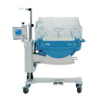
Operating Instructions Caleo, Software 2.n
Installing Accessories
Moving the control unit to the opposite side
for 38 mm pole
1 Loosen clamping screw to remove control unit. (Support
control unit to prevent it from dropping once clamping screw
is loosened.)
2 Loosen clamping screw to remove holder.
Upon delivery, the control unit is attached to the 38 mm dia.
tube of 310 mm length (38/310 pole).
This tube is secured for transport with a screw attachment.
If required, the tube can be detached (recommendation: ask for
assistance from qualified technical personnel):
3 Remove both caps from the tube. Insert a screwdriver into
the holes and release the tube.
To install control unit on the adjacent side:
z Slide holder over the other pole.
2 Tighten clamping screw to fix holder in position.
z Set control unit to the desired working height
1 Tighten clamping screw to secure control unit to the holder.
Mounting the control unit on the handle side
z Install basic pole (2M 50 680), see page 35.
z Screw in the extension pole 38/600 (2M 50 691) or
pole 38/310 (2M 50 688).
z Re-install the control unit as specified in the Assembly
Instructions.
CAUTION !
When mounting control unit to its pole, ensure that there is
sufficient space to swivel the control unit.
(see "Tilting the bed", page 48).
CAUTION !
Only qualified technical personnel may move the control unit
from the wall side to handle side or vice versa.
CAUTION !
Do not remove cable to the control unit from the cable guides
on the basic pole.
Make sure there is sufficient space to swivel and tilt the unit.