Plus and PSS Series - Lung Demand Valve
tm 1285.001 - August 2001
5:14
Screw-in Types - AE and N
Check handwheel freely rotates on connector assembly. If necessary
use assembly tool to assemble new O-ring to connector handwheel
assembly then using tool (3310679) screw connector handwheel
assembly into demand valve body until secure. Do Not overtighten.
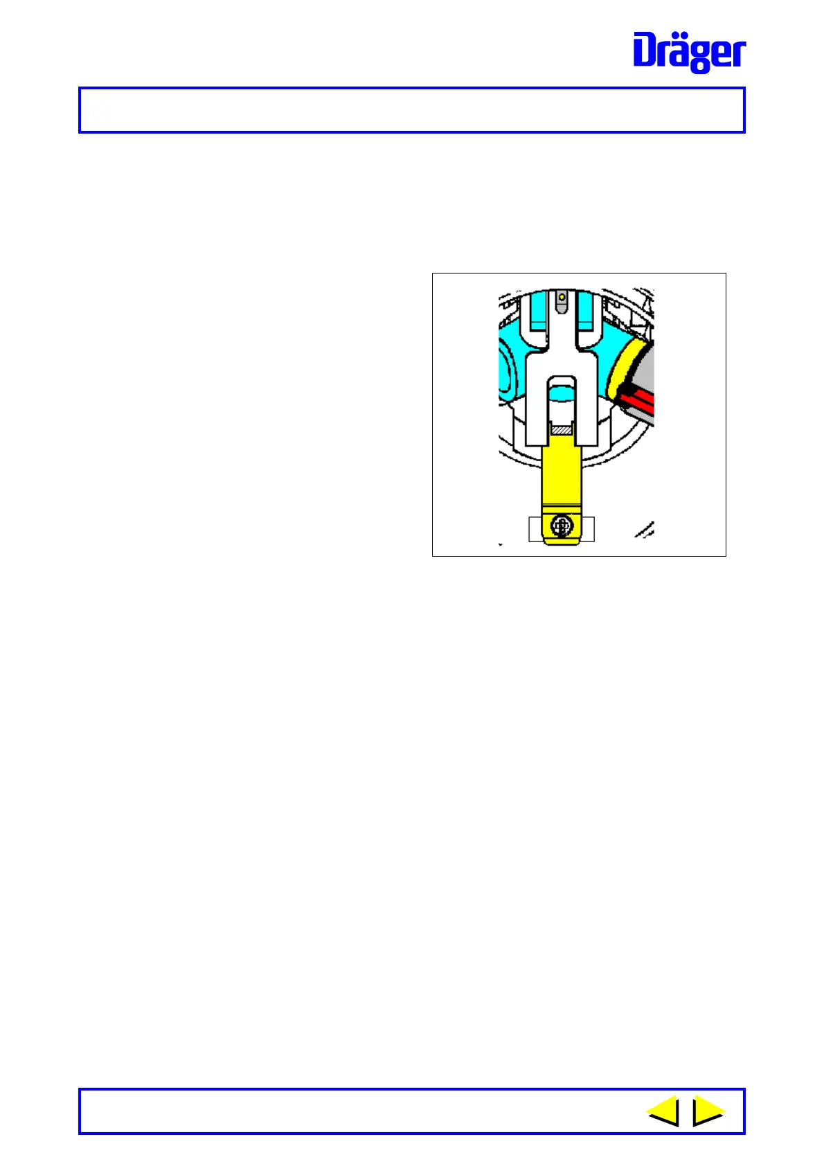
Fig. 13
1232
Refer to Figure 13.
8 When viewing inside body of the
lung demand valve - carefully
turn the connector anti-clockwise
until the first castellation tab of the
connector is visible and centred
between the internal slot in the
demand valve body. Lift the
locking arm and locate the
fingers of the locking arm either
side of the castellation preventing
rotation of the connector. Ensure
correct location then carefully
tighten screw to secure the
locking arm. Do Not overtighten.
9 Reassemble diaphragm - check that the outer bead of diaphragm is
located into the body of the demand valve and that the slip ring is
correctly located into recess in bead of diaphragm.
Types A and AE - Locate positive pressure spring of bayonet cap into the
recess in centre plate of diaphragm. Using plate spanner, inserted into radial
slots of the bayonet cap, lock bayonet cap to body then fold rubber cover
back over the front of the demand valve.
10 Press re-set button of types A and AE demand valves. Connect demand
valve to equipment and carry out Leak Test and Functional Test.
 Loading...