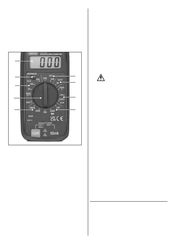
6.2 The Function Dial
Use the function dial (2) to select the value that most
accurately represents the anticipated measurement range
from the appropriate measurement type. If the value to be
measured is not known, set the function dial (2) to the
highest available range and reduce it until a suitable
reading is displayed.
The dial can be rotated 360° through the following
interface zones:
5 Fig.
(10)
(6)
(3)
(12)
(15)
(13)
(11)
(14)
(2)
10. DC voltage ranges
11. AC voltage ranges
12. Battery test function
13. DC current ranges
14. Resistance ranges
15. Diode test function
6.3 Voltage Measurement
1. Use the function dial (2) to select the appropriate
range from either the DC voltage (10) or AC voltage
(11) zones; see 6.2 The Function Dial.
2. Move the power switch (6) to the right to switch on the
device.
3. Position the probe contacts across the source of the
circuit to be measured, observing the correct polarity.
4. Enable the power to the circuit to be measured. The
voltage value is displayed on the LCD screen (3) along
with the voltage polarity if reversed.
6.4 DC Current Measurement
1. Use the function dial (2) to select the appropriate
range from the DC current ranges zone (13); see 6.2
The Function Dial.
2. Open the circuit to be measured and connect the
probes in series, using the correct polarity, to bridge
the gap.
3. Enable the power to the circuit to be measured. The
current value is displayed on the LCD screen (3).
6.5 Resistance Measurement
1. If the resistance to be tested is part of a circuit, switch
the circuit o, disconnect the power and allow all
capacitors to discharge before measurement.
WARNING! NEVER measure resistance
across a voltage source or on a powered
circuit.
2. Use the function dial (2) to select the appropriate
range from the resistance range zone (14); see 6.2 The
Function Dial.
3. Touch the probe contacts at either side of the
resistance to be measured. The current value is
displayed on the LCD screen (3).
6.6 Battery Test Function
Important: This product can be used to test batteries of up
to 9V.
1. Use the function dial (2) to select the battery test
function (12); see 6.2 The Function Dial.
2. Touch the probe contacts against the contacts of the
battery, observing the correct polarity. The current
value is displayed on the LCD screen (3).
6.7 Diode Testing
1. Use the function dial (2) to select the diode test
function (15); see 6.2 The Function Dial.
2. Touch the probe contacts against the contacts of the
diode, observing the correct polarity.
3. The approximate forward voltage drop of the diode is
displayed on the LCD screen (3); a typical diode
functioning normally will deliver a reading of 0.5–0.7.
7. Care and Disposal
Important: Disconnect the probes from the terminals and
any other source of voltage before performing any
maintenance on this product.
7.1 Maintenance and Storage
• Keep the product clean and free from dust, debris and
grease.
– 6 –