Premier by Draper
Page 2 of 4
.draperinc.com (765) 987-7999
+
+
I
I
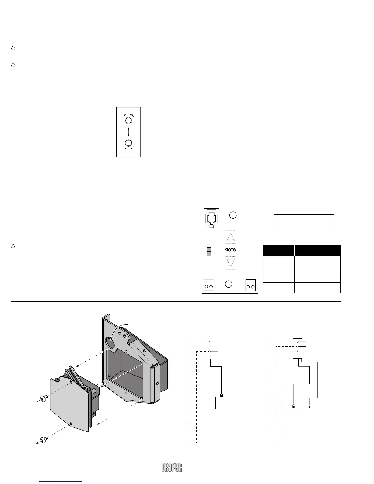
DOWN Limit
Countercloc
increases
down travel
UP Limit
Counterclockwise
increases
up travel
Limit Adjustments (Built-in Low Voltage Motors)
Please Note: Screen limits are factory set for optimum performance
of the screen. Any adjustment of these limits could void the warranty.
Please check with Draper prior to resetting screen limits.
(Height adjustments are made from wall switch)
1 Connect the switch to the motor via the terminal blocks, or via the
modular port using four conductor modular cable. When using modular
cable, the cable connectors MUST NOT be crimped in reverse, as with
standard telephone cable.
2 Set the slide switch to the lower position. Press and hold the DOWN button
on the switch to move the viewing surface to the desired lower limit. If the
screen moves in the opposite direction, release the DOWN button and
press and hold down the STOP button for four seconds. This will reverse
the operation of the UP and DOWN switches.
3 Move slider switch into center position. Wait a couple of seconds.
Please Note: If you move the slider switch from down to up in one
motion it sets the two limits in the same position.
4 Set the slide switch to the higher position. Move the viewing surface to the
desired upper limit by pressing and holding the UP button on the wall switch.
5 Return the slide switch to the center position to return to normal operation.
6 To set the viewing surface to an alternate format position, move the viewing
surface to the desired position and press the STOP button. Press and
hold STOP for at least three seconds to record the position.
Please Note: Pressing and releasing the UP button on the switch will
move the screen to its upper limit. Pressing and releasing the DOWN
button will move the screen to its lower limit.
While the motor is in motion, pressing STOP for less than two
seconds will stop the viewing surface at its present position.
Once the motor is stopped, pressing the STOP button will move the
viewing surface to its alternate format position.
Pressing and holding the STOP button, when the motor is at rest or in
motion, for at least three seconds will record a new alternate format
position.
POSITION
FUNCTION
DOWN
UP
CENTER
Set LOWER limit
Set UPPER limit
Normal Operation
POSITION
FUNCTION
DOWN
UP
CENTER
SetLOWER limit
SetUPPER limit
Normal Operation
S T O P
To Motor
with
Built-In
Slide
Switch
Back View
U
p
D
o
w
n
C
o
m
m
o
n
+
5V
DC
To Motor
with
Built-In
Low Voltage
Please Note: 5V DC must be
connected to be able to set
limits using the wall switch.
Limit Adjustments (Standard Motors/Quiet Motors)
Please Note: Screen limits are factory set for optimum performance of the
screen. Any adjustment of these limits could void the warranty. Please
check with Draper prior to resetting screen limits.
CAUTION: Always be prepared to shut screen off manually when new
adjustment is being tested. Screen may be severely damaged if viewing
surface is allowed to run too far up or too far down.
CAUTION: Be sure all switches are in “off” position before adjusting limit
switches.
The motor limit screws are normally located on the audience left of screen
roller, and the viewing surface rolls off the back of the roller. If the viewing
surface is coming off the front of the roller (motor on left), or the motor is on
the audience right of the screen roller (with viewing surface rolling off the
back), reverse the below instructions.
"DOWN" LIMIT ADJUSTMENT
To Reduce Screen Drop
1 Raise screen surface about 1' above
desired setting and turn off.
2 Turn the DOWN limit screw clockwise
(three screw turns = ½ roller revolution).
3 Test by running screen down and repeat steps
1 and 2 until desired position is reached.
To Increase Screen Drop
1 Run screen to the down limit.
2 With the down switch on, turn the DOWN limit
screw counterclockwise (three turns of screw equals ½ roller revolution)
to increase drop.
3 Test by running screen up about 1' and back down to new down limit.
4 Repeat steps 2 and 3 until desired position is reached.
"UP" LIMIT ADJUSTMENT
Screen is Running Too Far Up
1 Lower screen surface about 1' below desired setting and turn off.
2 Turn the UP limit screw clockwise (three screw turns = ½ roller revolution).
3 Test by running screen up.
4 Repeat steps 1 through 3 until desired position is reached.
Screen Needs to Run Up More
1 Run screen down about 1' and turn off.
2 With the up switch on, turn the UP limit screw counterclockwise
(three turns of screw equals ½ roller revolution).
3 Repeat steps 1 and 2 until desired position is reached.
CAUTION: Do NOT allow the dowel to wrap up over the roller when the
screen is running up! This could damage the screen.
Accessing Built-In Low Voltage Control Unit (LVC-IV)
To access the Built-In LVC-IV:
1 Remove the two (2) Torx head
screws from the motor
end of the screen housing.
2 Remove the access panel
with the LVC-IV from the
screen housing.
Remove two (2)
Torx head screws
from endcap
Remove
access panel
with LVC IV
Remove
access panel
with LVC IV
Electrical
Connection
Hole*
*A second electrical connection
hole is included in the screen
housing in order to separate Low
Voltage and High Voltage Wiring.
Wiring Diagrams—110-120V Motor and Quiet Motor
with Built-in Low Voltage Controller (LVC-IV)
Single Low Voltage Control
Internal Screen Wiring
White (Neutral)
Black
Green (Ground)
Dashed wiring
by electrician
To 110-120V Line
Multiple Low Voltage Controls
Internal Screen Wiring
White (Neutral)
Black
Green (Ground)
Dashed wiring
by electrician
To 110-120V Line
Wall Switch,
RF or IR
Receiver,
or integrated
control system
Wall Switch(es),
RF or IR
Receivers,
or integrated
control systems
Data
Cable
Single Low Voltage Control
Internal Screen Wiring
White (Neutral)
Black
Green (Ground)
Dashed wiring
by electrician
To 110-120V Line
Multiple Low Voltage Controls
Internal Screen Wiring
White (Neutral)
Black
Green (Ground)
Dashed wiring
by electrician
To 110-120V Line
Wall Switch,
RF or IR
Receiver,
or integrated
control system
Wall Switch(es),
RF or IR
Receivers,
or integrated
control systems
Data
Cable(s)
PLEASE NOTE:
Built-In LVC-IV will increase
overall case length by 2".
 Loading...