Premier by Draper
Page 4 of 4
.draperinc.com (765) 987-7999
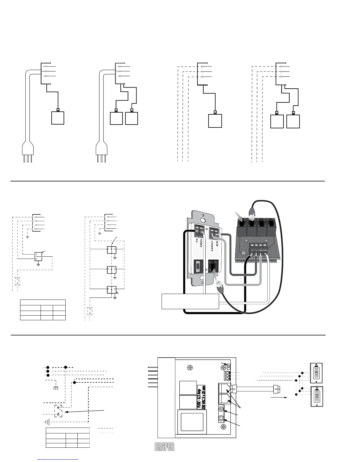
Dashed wiring by electrician
Low voltage wiring by others
RS232/485 Inputs/Outputs
Receiver
Button
Low Voltage Tr igger
3-28 VAC
IR Eye Input
3 Button Wall Switch
DOWN - Black
COM - White
UP - Red
Wall Switch
To
110-120 VAC
Line
White-Common to screen & 110 VAC Neutral
Red-to screen (directional)
Brown-to screen (directional)
Ye llow-to 110 VAC-Hot
Black-to 110 VAC-Hot
Green/Yellow (Ground)
White (Common)
Red (Up)
Black (Down)
nal Screen Wiring
Green/Yellow
(Motor Ground)
Electrically Straight
Data Cable to more
LVC-IV modules*
*A maximum of six (6)
LVC-IV modules can be
linked together.
N
L1
GND
Location of key
operated 0n-off
switch if furnished.
Wiring Diagram – LVC-IV
Wiring Diagrams (Standard and Quiet Motors)
Single Station Control
Internal Screen Wiring
White (Common)
Black (Directional)*
Red (Directional)*
Green/Ye llow (Ground)
Dashed wiring
by electrician
Control
switch
Single gang box by others
Min. 4" x 2
1
/8" x 1
7
/8" deep
Blue
Black
Red
Location of key
operated on-off
switch if furnished
To 110-120V Line
Multiple Station Control
Internal Screen Wiring
White (Common)
Black (Directional)*
Red (Directional)*
Green/Ye llow (Ground)
Dashed wiring
by electrician
Red
Red
Black
Blue
Blue
Cap off with wire
nut and tape
Black
Red
Blue
Black
Single gang box by others
Min. 4" x 2
1
/8" x 1
7
/8" deep.
3 shown. More or less equally
feasible.
Location of key
operated on-off
switch if furnished
To 110-120V Line
Motor Type Up Down
Standard Red Black
Quiet Red Black
*Motor Direction
Please Note: Do not wire motors in parallel.
Wiring Diagrams—Plug & Play 110-120V Motor
(Low Voltage Control Built Into Motor)
Single Low Voltage Control
Internal Screen Wiring
White (Neutral)
Black
Green (Ground)
Multiple Low Voltage Controls
Internal Screen Wiring
White (Neutral)
Black
Green (Ground)
Wall Switch,
RF or IR
Receiver,
or integrated
control system
Wall Switches,
RF or IR
Receivers,
or integrated
control systems
Data
Cable
Data
Cables
Plug
110-120V
Plug
Motor Type Up Down
Standard Red Black
Quiet Red Black
*Motor Direction
Wiring Diagrams—110-120V Motor
(Low Voltage Control Built Into Motor)
Single Low Voltage Control
Internal Screen Wiring
White (Neutral)
Black
Green (Ground)
Multiple Low Voltage Controls
Internal Screen Wiring
White (Neutral)
Black
Green (Ground)
Wall Switch,
RF or IR
Receiver,
or integrated
control system
Wall Switches,
RF or IR
Receivers,
or integrated
control systems
Data
Cable
Data
Cables
110-120V Line To 110-120V Line
Built-in Low Voltage Motor: Switch-to-Motor—
Dry Contacts or Data Cable connection
INSERT MOTOR DATA
CABLE HERE
Please Note:
This Splitter/Jack
is located inside the
motor-end endcap
of your screen.
To access, remove
access panel from
endcap.
Back of
wall switch.
Please Note:
Although both Dry
Contact and Data
Cable connections
are shown, you
should only use
one connection
type per motor.
Data Cables to switches
or to additional motorscan
be plugged into any of the
three open jacks.
Please Note: 5V DC must be
connected to be able to set
limits using the wall switch.



 To Previous Page