- 18 -
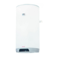
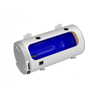
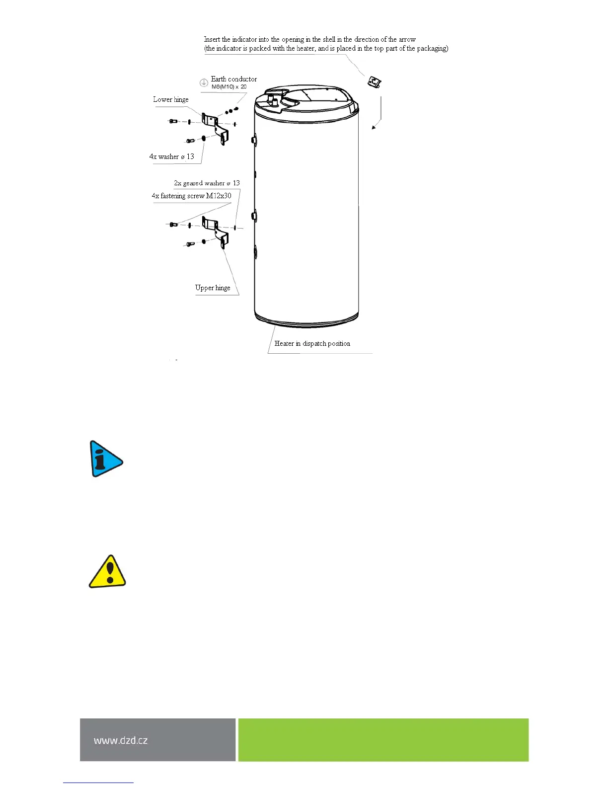
Figure 9
2.3 PLUMBING FIXTURE
Tanks are connected to plumbing fixtures as shown in (Figure 10, Figure 11, Figure 12). For
potential disconnection of the tank, utility water inlets and outlets must be provided with Js
3/4“ screw coupling. If the hot utility water (HSW) distribution is equipped with circulation
circuit, the reverse pipe is connected to the inlet identified as CIRCULATION. Types 100, 125,
160 NTR and 100, 125, 160 NTR / HV are equipped with drain outlet. In 200 and 250 NTR(R)
types, the HSW inlet has to be provided with a “T” fixture with a drain valve. The tank shall
be equipped with safety valve to ensure operation. The safety valve is mounted on the cold
water inlet identified with a blue ring.
Every hot utility water pressure tank shall be equipped with membrane spring loaded with
safety valve. Safety valve shall be easily accessible, fitted as close as possible to the tank. The
inlet pipes must have at least the same clearance as the safety valve. Safety valve is placed
high enough to secure dripping water drain by gravity. We recommend mounting the safety
valve onto a branch pipe. This allows easier exchange without having to drain the water from
the heater. Safety valves with fixed pressure settings from the manufacturer are used for the
assembly. The starting pressure of the safety valve must be identical to the maximum
allowed pressure of the tank, and at least 20 % higher than is the maximum pressure in the
water main (Table 10). If the water main pressure exceeds such value, a reduction valve
must be added to the system. No closing armature may be mounted between the tank and
the safety valve. During assembly, follow the guide provided by the safety equipment
manufacturer.