- 6 -
1.3 DESIGN AND GENERAL HEATER DIMENSIONS
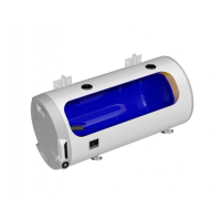
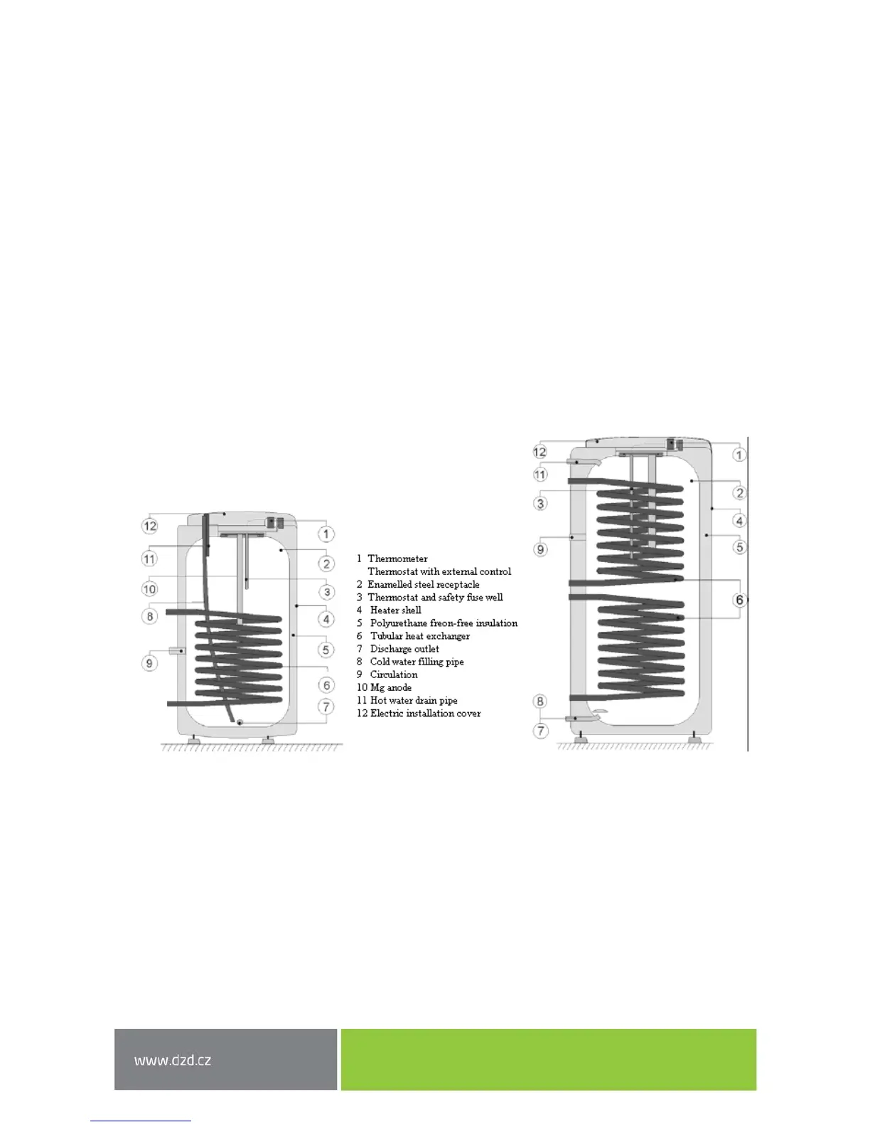
The tank receptacle is made of steel plate and tested at 0.9 MPa of overpressure. The inside of the
receptacle is enamelled. A flange is welded onto the lower bottom of the receptacle with a flange lid
screwed onto it. A sealing ring is inserted between the flange lid and the flange. Thermowells for
thermostat sensors and thermometer installation are placed in the flange lid. An anode rod is mounted
onto the M8 nut. The water reservoir is insulated by means of polyurethane foam. Electric wiring is placed
underneath the plastic removable cover. The temperature of water can be set using the thermostat. Heat
exchanger(s) is/are welded onto the pressure tank.
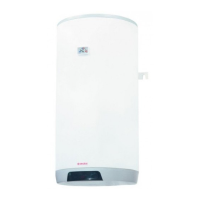
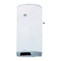
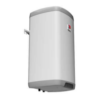
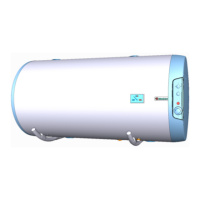
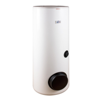
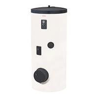
Description of basic parts of the tank – by individual types (Figure 1, Figure 2, Figure 3, Figure 4).
Heater dimensions (Figure 5, Figure 6, Figure 7, Figure 8) and (Table 2, Table 4, Table 6, Table 8).
Technical description: OKC 100 NTR, OKC 125 NTR, OKC 160 NTR, OKC 200 NTR, OKC 250 NTR, OKC 200
NTRR, OKC 250 NTRR
Figure 1