- 6 -
1.3 DESIGN AND GENERAL HEATER DIMENSIONS
The heater tank is made of a steel plate and tested by 0.9 MPa overpressure. The inside of the receptacle is
enamelled. A flange is welded onto the bottom of the tank with a flange lid screwed to it. A sealing ring is
inserted between the flange lid and the flange. Thermowells for placing a heating element, thermostat
sensors and safety fuses are located in the flange lid. An anode rod is mounted onto the M8 nut. Electric
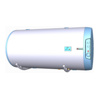
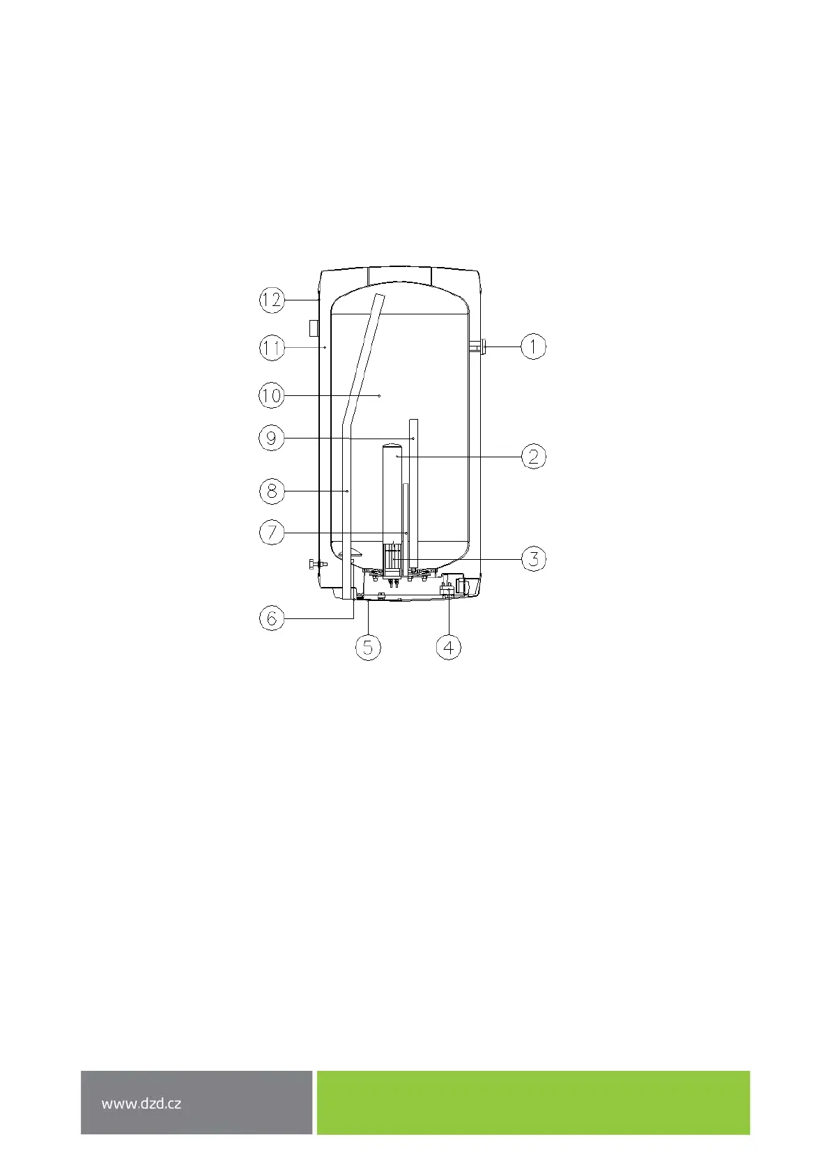
wiring is placed underneath the plastic removable cover. Description of basic parts of the heater – Figure 1.
Heater dimensions – Figure 2 and Table 2, Figure 3 and Table 3.
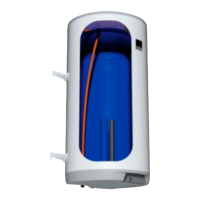
Figure 1
1. Temperature indicator
2. Heating element well
3. Ceramic heating element 2200W
4. Service thermostat with external
control and safety pipe
5. Electric installation cover
6. Cold water supply pipe
7. Thermowell
8. Hot water withdrawal pipe
9. Mg anode
10. Enamelled steel receptacle
11. Polyurethane insulation
12. Heater shell