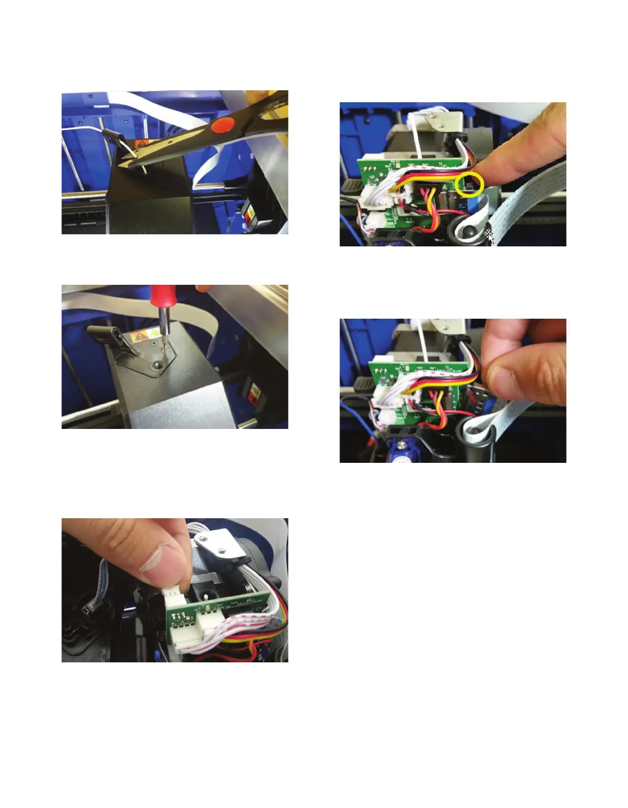
Step 2: Remove Top Cover of Extruder
1
. Cut the filament just before the intake on the top of the
extruder.
Figure 3
2. Unscrew the two screws on the top of the filament guide
bracket.
Figure 4: Extruder cover removal
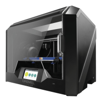
3. Remove the top cover.
4. Carefully unplug filament runout switch from the extruder
circuit board, ensuring to pull from the plastic plug and not
the wires; pulling the wires can damage the connection to
the extruder.
Figure 5: Runout switch connector being disconnected
from extruder PCBA
Step 3: Removing the Shielded Circuit Cable
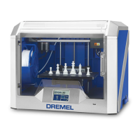
1
. Using the 2 black push pins (top encircled yellow, bottom
hidden) of the shielded circuit ribbon cable, push down to
release it from the circuit board.
Figure 6: Disconnect shielded circuit ribbon cable
from extruder PCBA
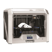
2. Remove the connector from the circuit board and pull up
on the cable. Always use great care when handling a
shielded circuit cable.
Figure 7: Removal of ribbon cable from extruder housing
3. Set aside the cable within the machine, making sure there
are no sharp kinks or turns produced.
2