24
4-2-21 Overload pre-alarm setting
1) No. 95 OL.Pre-Alarm (overload pre-alarm setting)
When the current set for overload rate (see 4-1-9) is exceeded, the internal overload counter starts counting.
When the counter exceeds the overload pre-alarm setting, OL.Pre-Alarm is output to the multifunction output
terminal. (When the overload condition continues and the overload counter reaches 100%, overload protection
is provided to stop the inverter.)
4-2-22 Inverter LED indication item selection
1) No. 96 LED-Disp.Sel (inverter LED indication item selection)
The LED indication items at the upper part of the unit can be selected from the following.
4-2-23 Alarm data clear
1) No. 97 ALM_data clr (fault history clear)
[1] yes
[2] no
}
To clear alarm data, set it to yes. After the clearing, it is automatically set back to no.
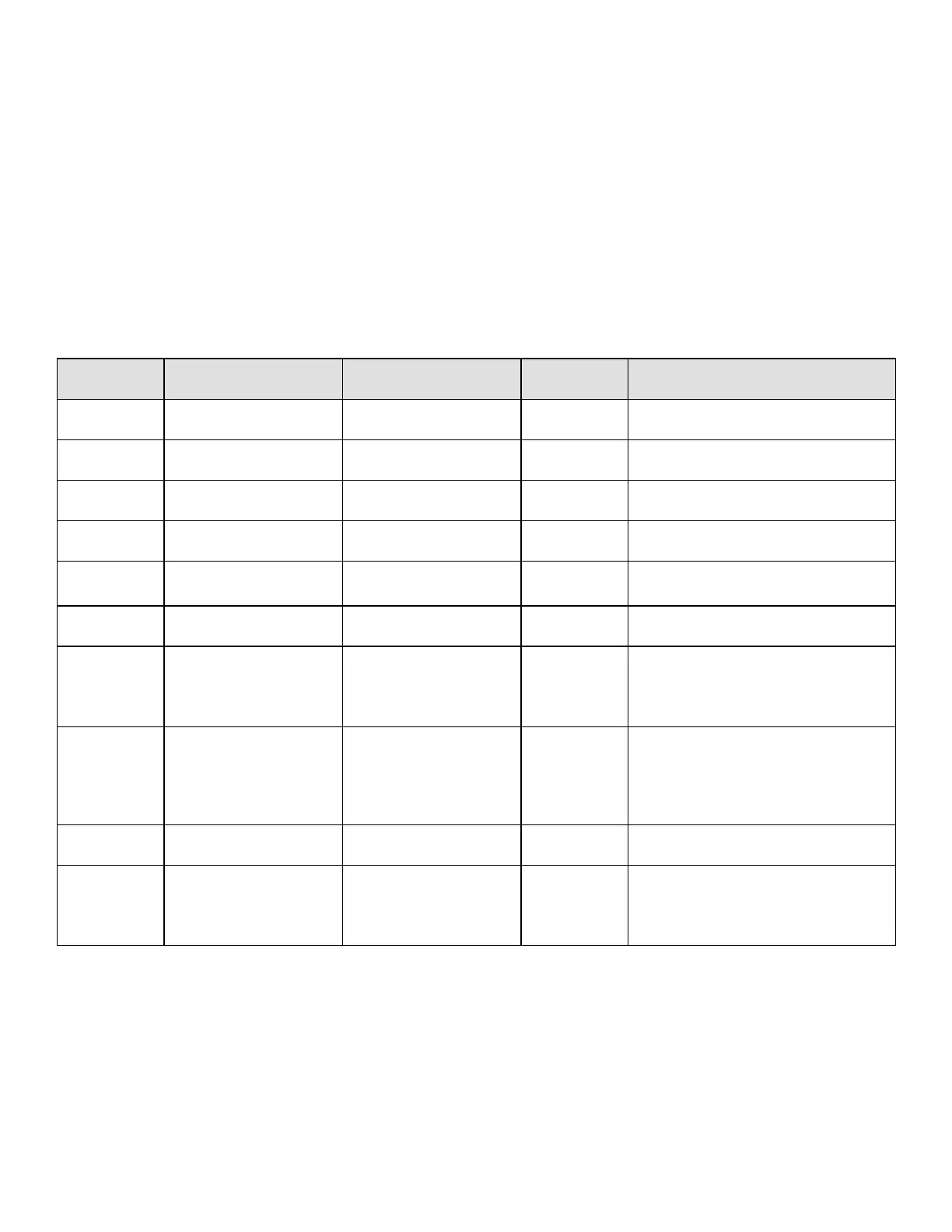
Table 16 Inverter LED indication
No. LCD Monitor indications Unit Remarks
0 Fout Output frequency Hz
1 Fref Reference frequency Hz
2 Iout Output current A
3 Vout Output voltage V
4 Torq out Torque (torque current) %
Current for the same phase as the
output voltage is indicated.
5 Vdc DC voltage V
6 Motor Speed Synchronous motor RPM rpm
For ASR operation, number of actual
rotations is indicated. For other
operations, the number obtained based
on the the frequency is indicated.
7 OL counter Overload counter %
When the rated motor current is
exceeded, the counter starts counting.
After this, when the counter reaches
100%, the overload protection starts.
(When OL.Set=100%)
8 Line Speed Line Speed
9 ROM Version ROM version
The XX.XX portion of the ROM
software version VF61-XX-XX is
indicated. Alphabetic characters A, B,
....., however, are converted to 0, 1, .....
 Loading...