No. Code No. LCD Setting
1 No. 24 DB.V Dynamic brake operating voltage
2 No. 25 0-10V.Gain
Frequency setting input + side (0V to
10V) gain
3 No. 26 -10-0V.Gain
Frequency setting input - side (-10V to
0V) gain
4 No. 27 Term-9.Gain Terminal (9) (analog output) gain
5 No. 28 Term-9.Ofset Terminal (9) (analog output) offset
6 No. 29 VDC.DET.Gain DC voltage detection gain
7 No. 30 CRT.DET.Gain Output current detection gain
8 No. 31 FCL.Level FCL level
4-3 Special Setting Items 2 (Sp.set-2)
When SP.set-2 is selected at code No. 16 (selection of special setting items) in the basic setting items, the
functions for the following code numbers 17-31 are set.
Even when code No. 16 is already set to Sp.set-2, select Sp.set-2 again to set those code numbers.
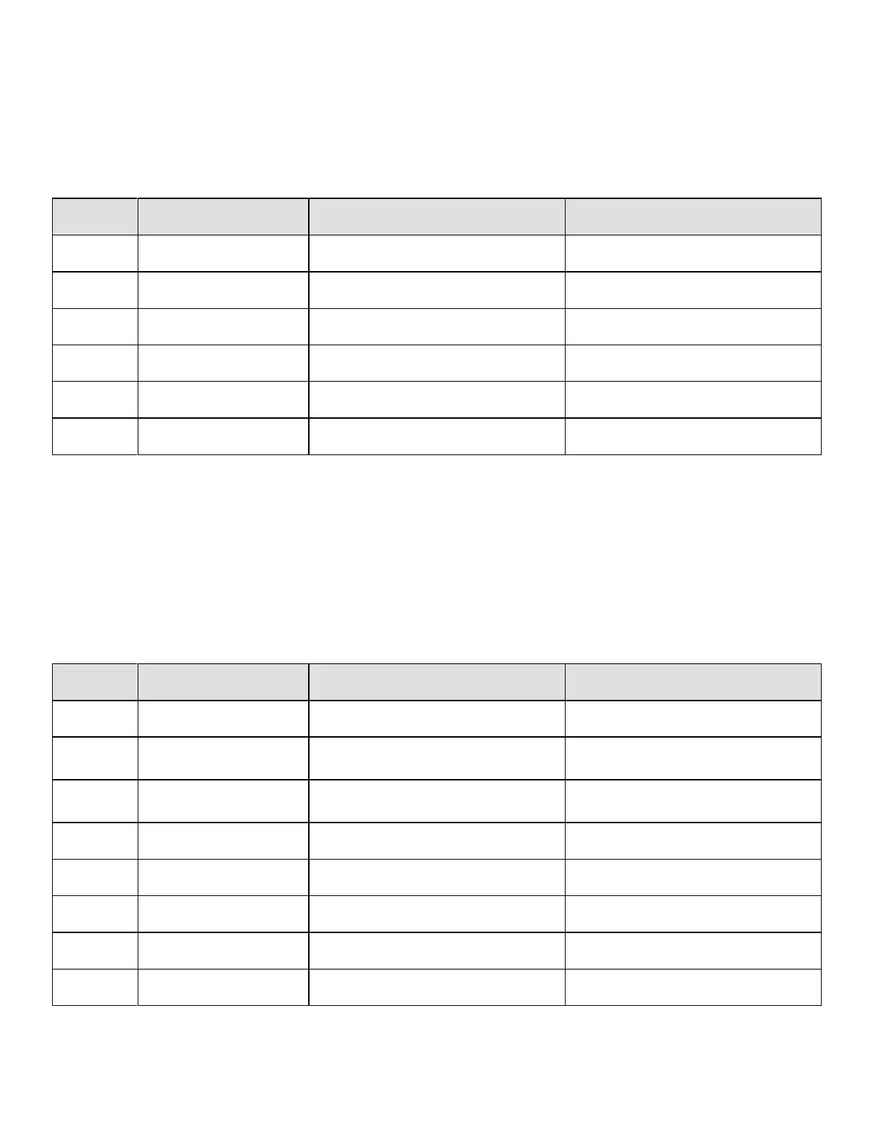
4-3-1 Input of motor constants
Before performing auto tuning, input the following motor constants inscribed on the motor rating plate.
No. Code No. LCD Setting
1 No. 17 Motor.Cap Rated motor capacity
2 No. 18 Motor.V Rated motor voltage
3 No. 19 Motor.I Rated motor current
4 No. 20 Motor.F Rated motor frequency
5 No. 21 Motor.RPM Rated motor RPM
6 No. 22 Motor.Pole Number of motor poles
4-3-2 Primary resistance for the motor.
The primary resistance is automatically set by auto tuning. It can also be adjusted at the console.
1) No. 23 Motor.R1 Primary resistance drop of the motor.
4-3-3 Others
The following code numbers are internally adjusted in our company. Do not change those codes unless the PC
board is replaced.
Table 17 Motor constants
Table 18 Code to be internally adjusted
25