7
(Note 1) Program memory error and insufficient voltage (including instantaneous power failure) are only
indicated at the LED in the inverter and not displayed at the console.
(Note 2) When an alarm other than Start Failure is indicated, the inverter stops.
(Note 3) Retry is possible for DC Overvoltage Protection.
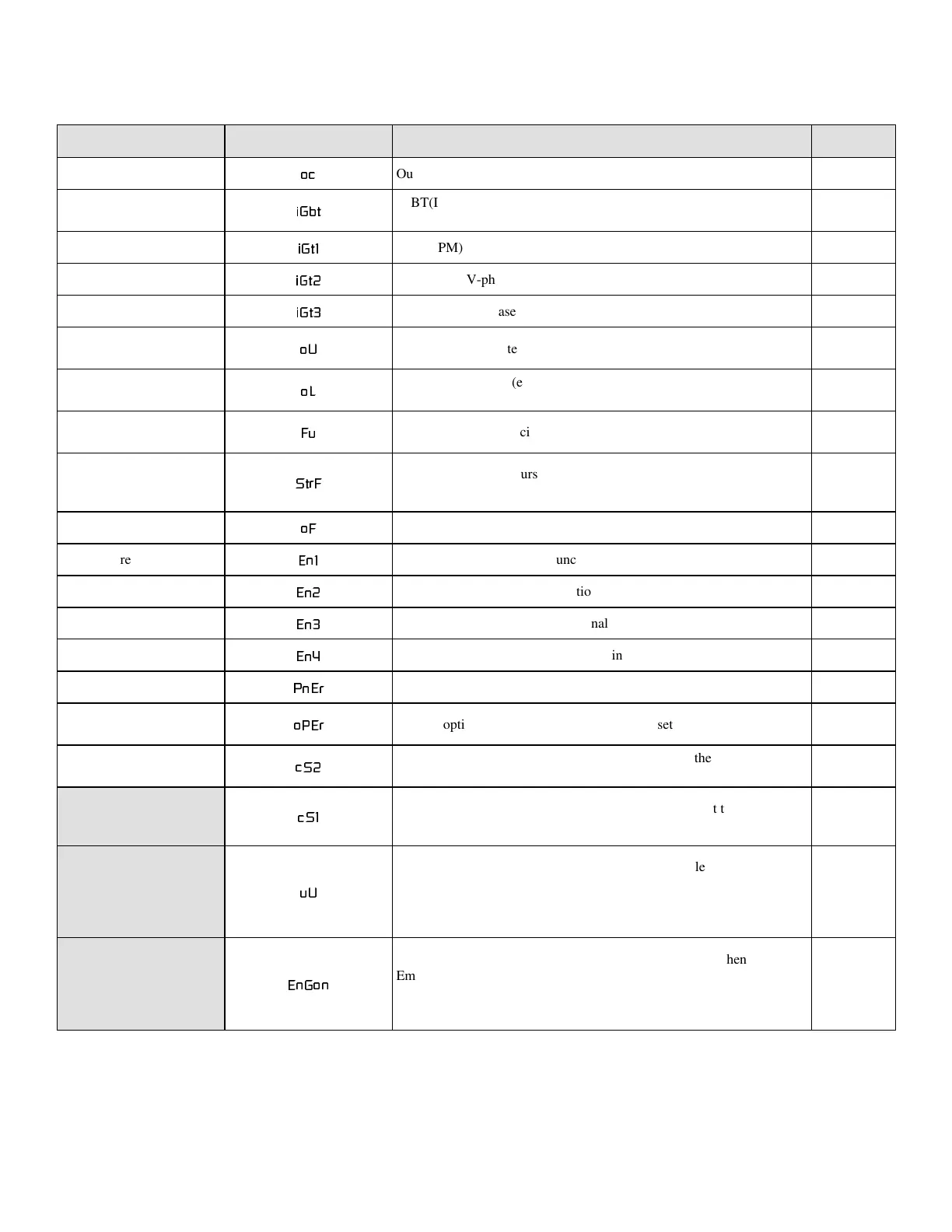
Table 5 Alarm Indications.
LCD LED Error/fault/failure description Contact
Overcurrent
RF
Output overcurrent protection on
IGBT Fault
L*EW
IGBT(IPM) fault. 7.5kW or less (overcurrent, overload, gate
power failure, overheat)
on
IGBT(U) Fault
L*W
IGBT(IPM) U-phase fault. 11kW or more. on
IGBT(V) Fault
L*W
IGBT(IPM) V-phase fault. 11kW or more. on
IGBT(W) Fault
L*W
IGBT(IPM) W-phase fault. 11kW or more. on
Over Voltage
R8
DC overvoltage protection. Retry is possible. (Note 3) on
Over Load
R/
Overload protection (electronic heat). Based on the rated motor
current.
on
Blown DC Fuse
)X
The fuse for the main circuit is blown. Retry is possible. on
Start Failure
6WU)
Start failure. This occurs in such a case that restart is inhibited
after instantaneous power failure. (Note 2)
on
Over Freq
R)
Excess frequency. on
EXT Failure-1
(Q
External failure 1 (for multifunctional input) on
EXT Failure-2
(Q
External failure 2 (for multifunctional input) on
EXT Failure-3
(Q
External failure 3 (for multifunctional input) on
EXT Failure-4
(Q
External failure 4 (for multifunctional input) on
Panel Error
3Q(U
Console panel error on
Option Error
R3(U
Internal option board error. This occurs when setting the option. on
EEPROM Error
F6
EEPROM (memory for data storage) error. This has the highest
indication priority.
on
F6
Program memory (ROM) error. This is displayed only at the LED
and the console goes into serial communication error. (Note 1)
on
X8
Insufficient voltage (power failure). Restart is possible without
resetting under the condition that the error is displayed only at the
LED. To turn off the indication, set the inverter in the operation
mode and press the [RST] key. (Note 1)
off
(Q*RQ
Emergency stop (multifunctional input terminal) is on. (When
Emergency stop is turned off, the indication is erased. When an
other error has occured, it has indication precedence over this
error.)
X
2. Alarm Indications
When an error or failure occurs in the inverter, its message and short name are displayed at the console and/or
the 5-digit 7-segment LED.