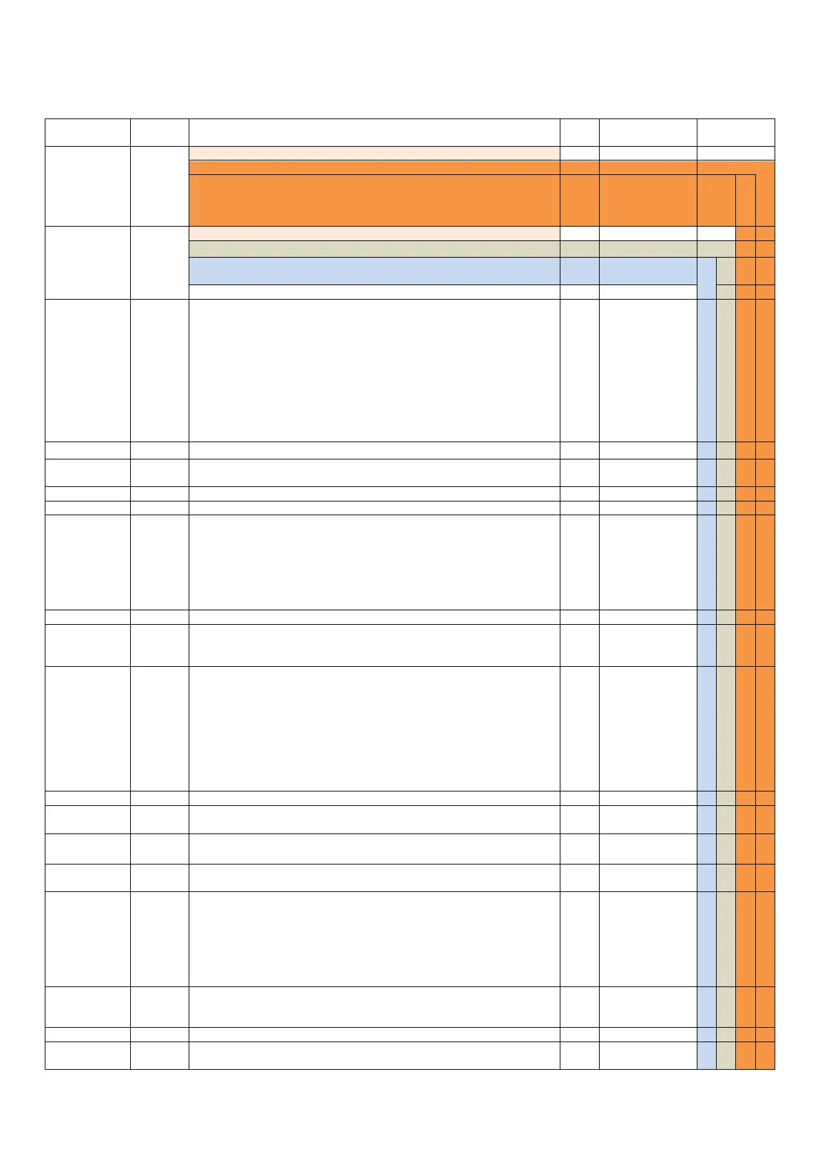
16
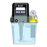
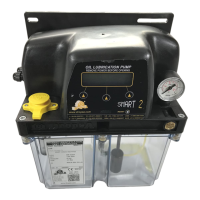
8.7.1 COMPLETE LIST OF PARAMETERS FOR AUTOMATIC VERSIONS
APPLICABILITY column of the table shows the possible combinations of the parameters, in relation to the work mode selection
(using CYCLE END parameter) and the control type of lubrication cycle (using LUBE TYPE parameter).
SELECTS THE OPERATING MODE:
Lubrication Cycle completed when the cycle sensor confirms correct lubrication
Both Standby and Lubrication Phase determined by external signal
SELECTS THE CYCLE MONITORING:
Determines Standby Phase Timing
Whichever of above 2 events occurs first
A set number of external PULSE signals
By PULSE signals. However, if PAUSE TIME is reached, an alarm will be given
Timeout counter determines max time permissible for cycle completion before a
timeout alarm is generated.
How long the pump will run
Number of Lubrication Cycles to complete a Lubrication Phase
Determines state at power on:
Start in Standby Phase
Start in Lubrication phase
Resume from power down state
How REMOTE ALARM is managed
Relay is powered off during alarm standard NO/NC
A Pulse Coded Alarm signal is given (for details see section 9.1)
Determines what Alarm conditions should stop the Lubrication cycles.
Never stop the lubrication cycle
All but min Level stops the pump
Only minimum level alarm stops the pump
Time between two Lubrication Cycles within the Lubrication Phase
When the pressure switch is made, how long to keep the pump running to
ensure that the signal is genuine and not a pressure spike
In enabled, the pump will suspend operation if the external suspend signal is
present
In Pulse Mode, if pulses are not received within this time the pump will be in
alarm
In Cycle Mode sets the number of external pulses for standby. This parameter
can be used in conjunction with the pause timer. If set to zero the standby will
be based exclusively on the ‘standby timer’ setting.
In Pulse mode, sets the duration (in pulses) for standby phase.
0 –250
(cycle mode)
1-60000
(PULSE mode)
The multiplies is used to increase the order of magniture of the standby counter.
For example sending a multiplier of 100 and a standby counter of 52 will result in
a standby value of 5200
The Duration of the Lubrication cycle (in PULSE Mode)
RESET TO FACTORY DEFAULT SETTINGS