DRUCKER DIAGNOSTICS SM006
MODEL 642E SERVICE MANUAL REV: A 9
j) Fasten the guard bowl to the base with six 5/32 nominal diameter, low-profile head
rivets.
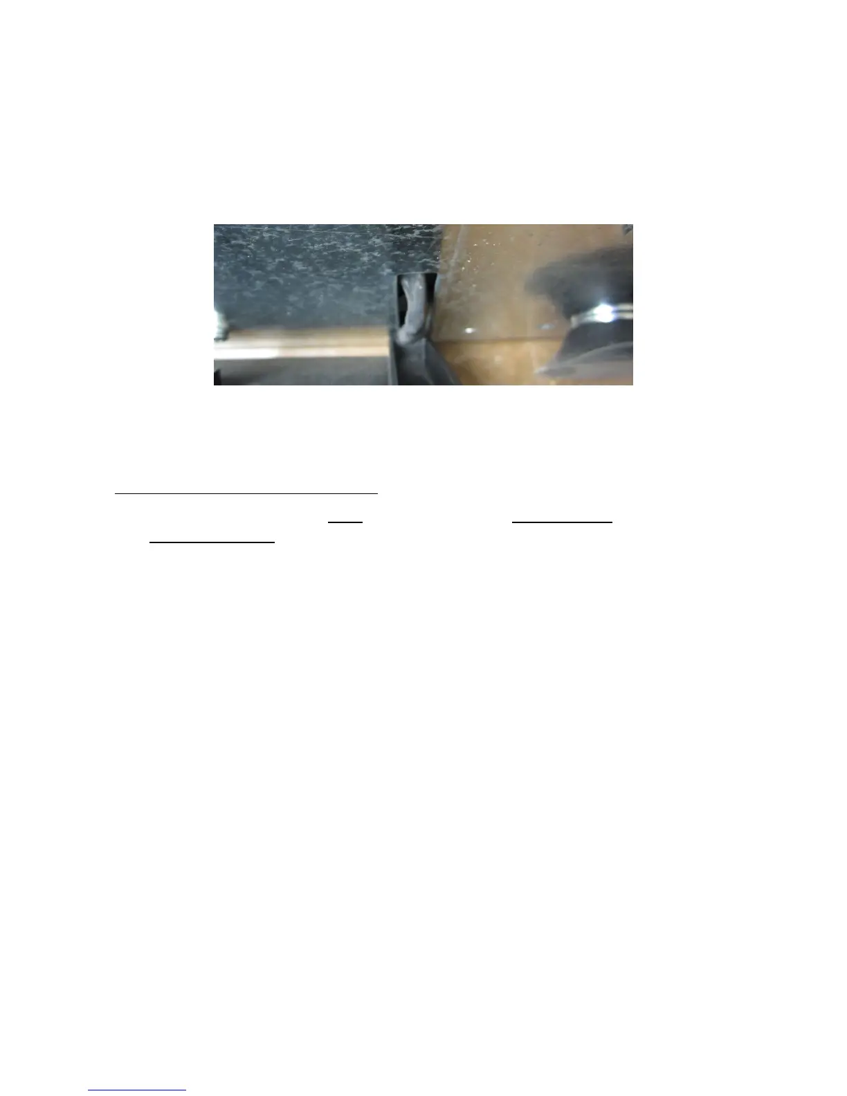
k) Install the exhaust air cover with three 5/32” rivets. Make certain that the motor wire
harness is contained within the cover’s wire channel. See fig 2.
Fig 2
l) Replace the zip tie removed earlier
m) The lower assembly is complete.
6.13 Power Connections and Final Assembly
IMPORTANT: These steps must be followed to avoid personal harm and to avoid
damaging the PCB.
a) Make certain that the lower assembly is unplugged from the mains supply.
b) Connect the motor/power connector to J5 on the PCB
c) Carefully place the cabinet onto the base taking care not to pinch any wires between the
two.
d) Complete the assembly by replacing the six #8 screws, washers and lock washers with a
#2 Phillips driver.