Timing Gear - General
The rear of each pump houses a pair of timing gears which synchronise the rotors to ensure
that they do not come into contact with each other.
The gears have internal splines which mate onto the respective shaft splines. Each gear is
retained on the shaft by a circlip which locates into a groove in the shaft.
Timing Gear - Removal
To aid removal, each gear is provided with threaded holes for fitting extractor tools. The
following procedure is recommended to remove the timing gears:
1. See Replacing Rear Oil Seals section for details of removing gearcase cover.
2. If pump is fitted with hydraulic drive, the drive adaptor must be removed from the
gear first. This can be done by removing the four socket head screws which retain
the adaptor to the gear.
3. Use a pair of circlip pliers to remove circlips.
4. Before removing gears, note the position of the timing marks. The timing marks will
be used on assembly. See Fig 9b and 9c, page 17.
5. Progressively ease each gear from its shaft, using a puller if necessary.
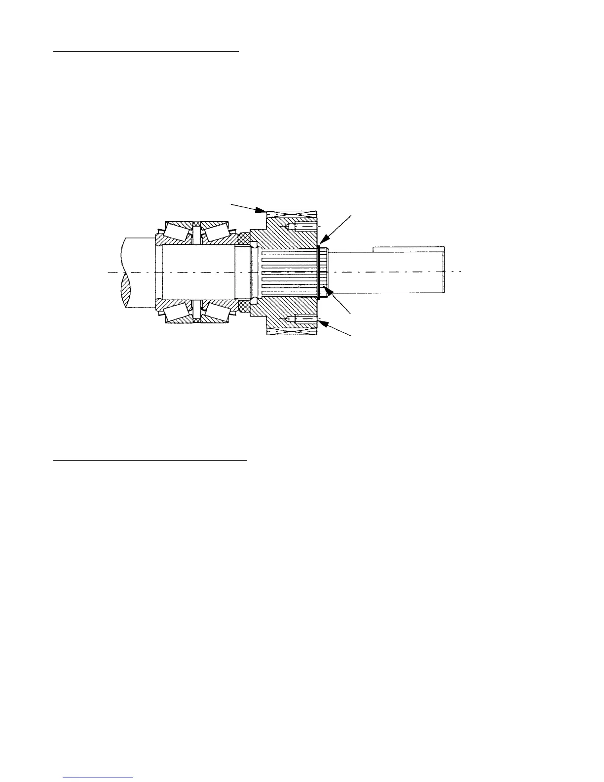
Timing Gear
Circlip
Spline
Extraction Holes
Fig. 4
Page 12