Shafts - General
Each pump has two shafts which are housed within the gearcase. Both shafts have been
manufactured with two splines for rotor and timing gear location, In the standard pump the
'drive shaft' is easily identified as it is the longest of the two shafts, and has a keyway ma-
chined into it. This is the bottom shaft. For pumps fitted with hydraulic drive, the drive shaft
has an adaptor fitted to the timing gear, and is the top shaft. The remaining shaft is referred
to as the 'auxiliary shaft'.
Shafts - Refitting Assemblies
1. Locate the shaft alignment spacer into the bottom rear bearing bore of the gearcase.
Fig. 7.
2. Fit the drive shaft into the appropriate gearcase bore, which is on the same center
line as the coupled drive unit being used (standard drive - bottom, hydraulic drive -
top).
3. Fit the auxiliary shaft into the remaining bore of the gearcase.
4. The front bearing retainers can be located in position and tightened to the torque
required. Note: DO NOT USE silicon sealant at this stage.
5. Fit both rotors as detailed in Rotor Assembly section.
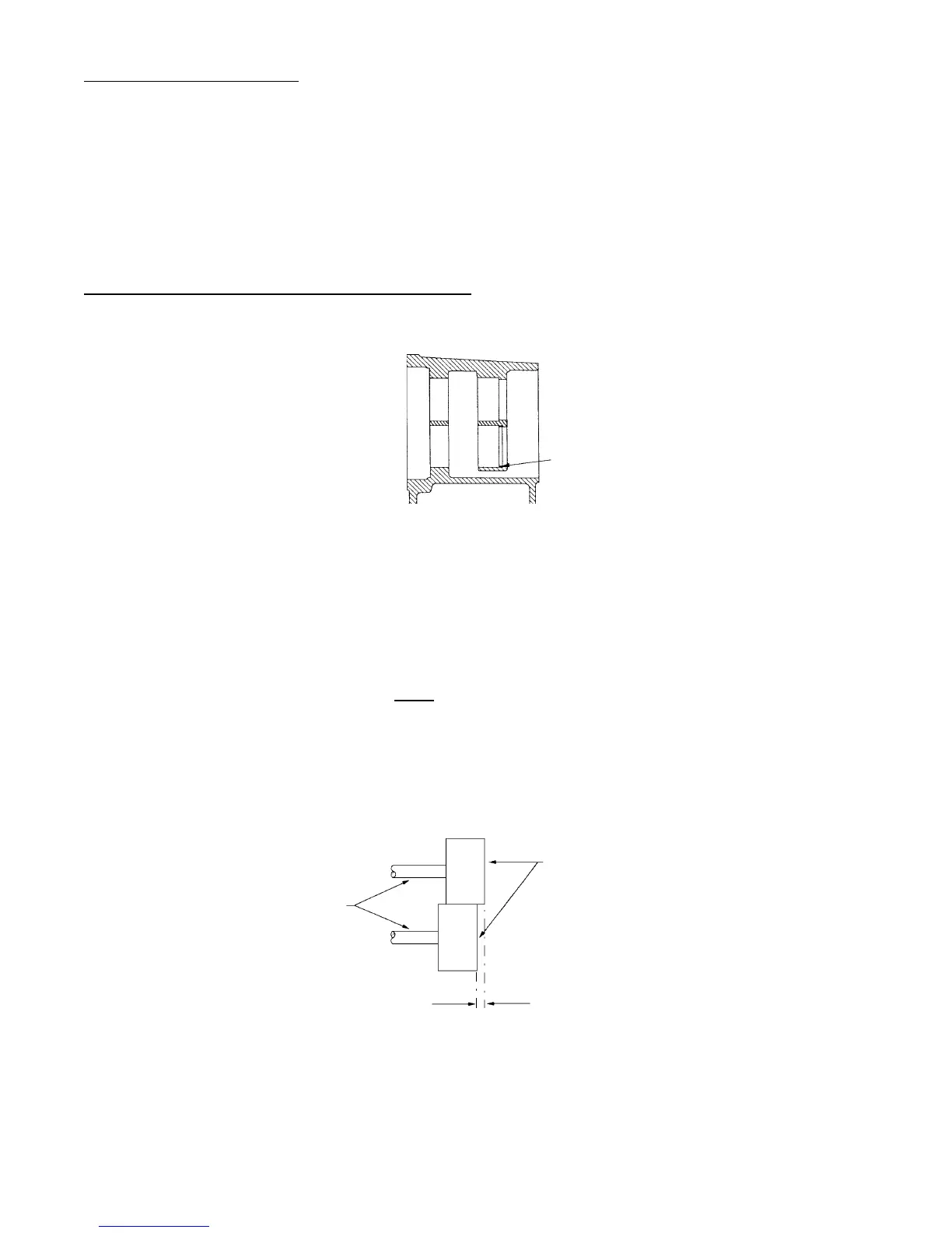
6. The difference in axial displacement should be measured using a depth micrometer.
By comparing the differences between each rotor, the axial displacement is
recorded, see Fig. 8.
7. If the axial displacement is above 0.012mm (0.0005"), the appropriate shaft should
be removed to gain access to the shaft alignment spacer. The spacer should be
ground down to give the correct axial displacement.
8. Once the correct displacement is achieved, the silicon sealant should be applied to
the seal retainers, and screws retightened to specific torque requirements.
Shaft
Alignment
Spacer
Fig. 7
Rotors
Shafts
Axial Displacement
Fig. 8
Page 15