Rotor Assembly
1. Before the rotors can be refitted onto their respective shafts, the sealing o-rings must be
inspected for damage and replaced as necessary.
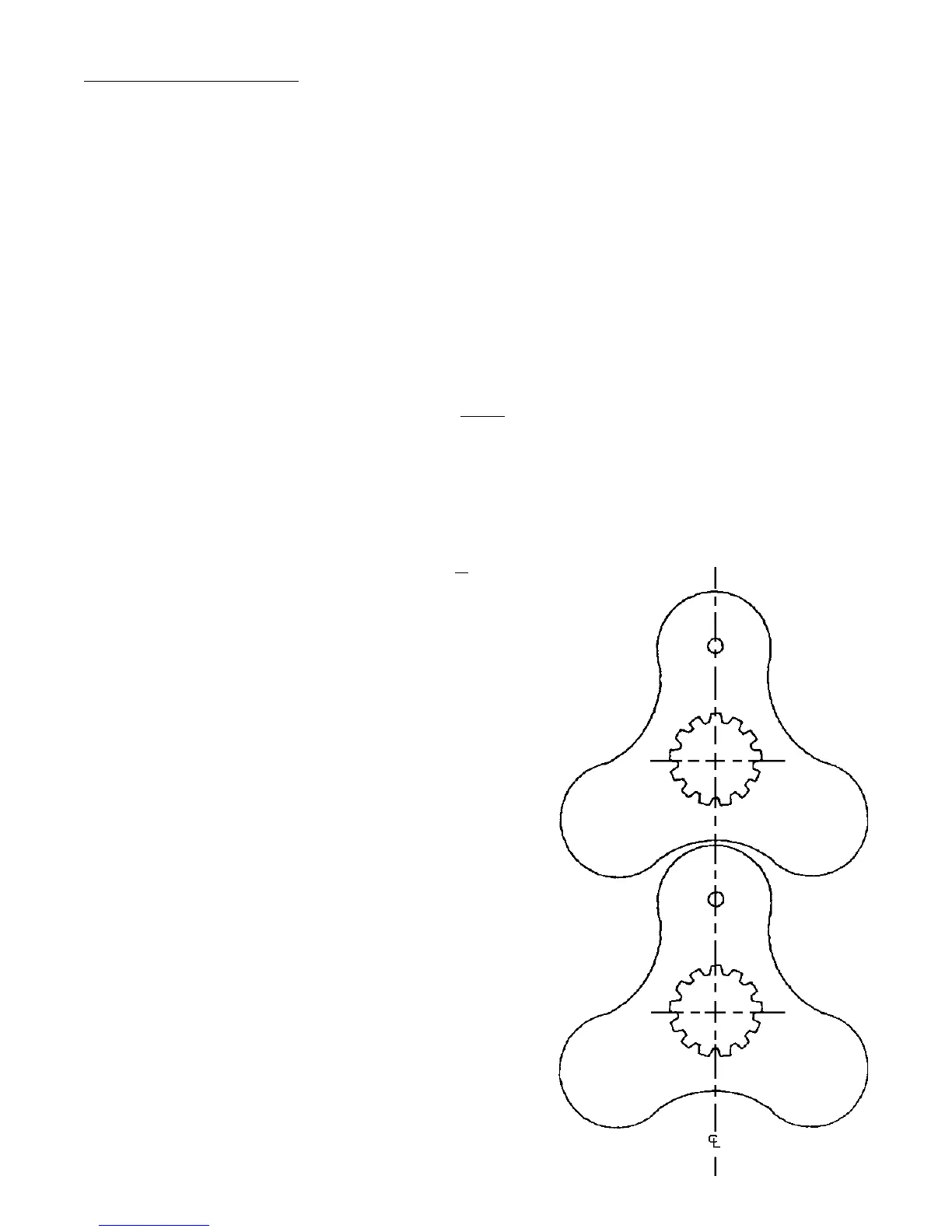
2. To assist assembly, each rotor has a small dimple machined into it to identify the center
line of the master lobe. These must be visible from the front of the pump,
indicating that the rotors have been fitted the correct way round.
3. If rotor positions were marked prior to removal, then the rotors should be refitted one at
a time, being careful to line up the marks.
4. If no marks were made, and the pump is not fitted with hydraulic drive, then:
- Rotate the pump so that the keyway in the drive shaft is pointing vertically upwards.
- Fit rotors one at a time so that each dimple is pointing upwards on the vertical centerline.
5. If no marks were made and the pump is fitted with hydraulic drive,
then:
- Fit the first rotor on the shaft in any position.
- Rotate the pump so that the dimple on the first rotor is pointing
vertical upwards on the vertical centerline.
- Fit the second rotor on the bottom shaft, ensuring that the
dimple is also pointing upwards on the vertical centerline.
6. Rotate the shaft by hand to ensure there is no
metal to metal contact between the rotors.
7. The rotor nuts can now be tightened onto the shafts to the
recommended torque values.
8. Examine the front cover o-ring and replace as
necassary. Locate front cover and tighten the front
cover nuts to the recommended torque values.
Fig. 2 - Rotors
Page 9