Series PC Manual V 1.0 - Rev. 3 – 03/01/01 DS Europe
15
It is possible to program the transducer to work with both cursors and use one or the other
as needs be.
In case where, during operating, one or two of the cursors are not present on the
measuring probe wee see that:
• analog outputs: the output value goes up to a fixed value of 10 Vcc, until the cursor
magnet is inserted.
• serial output: the absence of the cursors is signalled by the number 9999999 until the
cursor is reinserted in the probe.
The minimum distance between the two cursors, in order not to interfere one with
the other is 52 mm.
Smaller distances can generate interference between magnetic fields and there is even
the possibility to have errors or even to lose the detection of one of the cursors.
9.6. ANALOG OUTPUTS
The analog outputs available in the series PC are maximum two as follows:
• From 0 to + 10 V.
• From 0 to + 5 V
• From 4 to 20 mA.
• From 0 to 20 mA.
It is possible to match to one analog output the cursor displacement (straight or reversed)
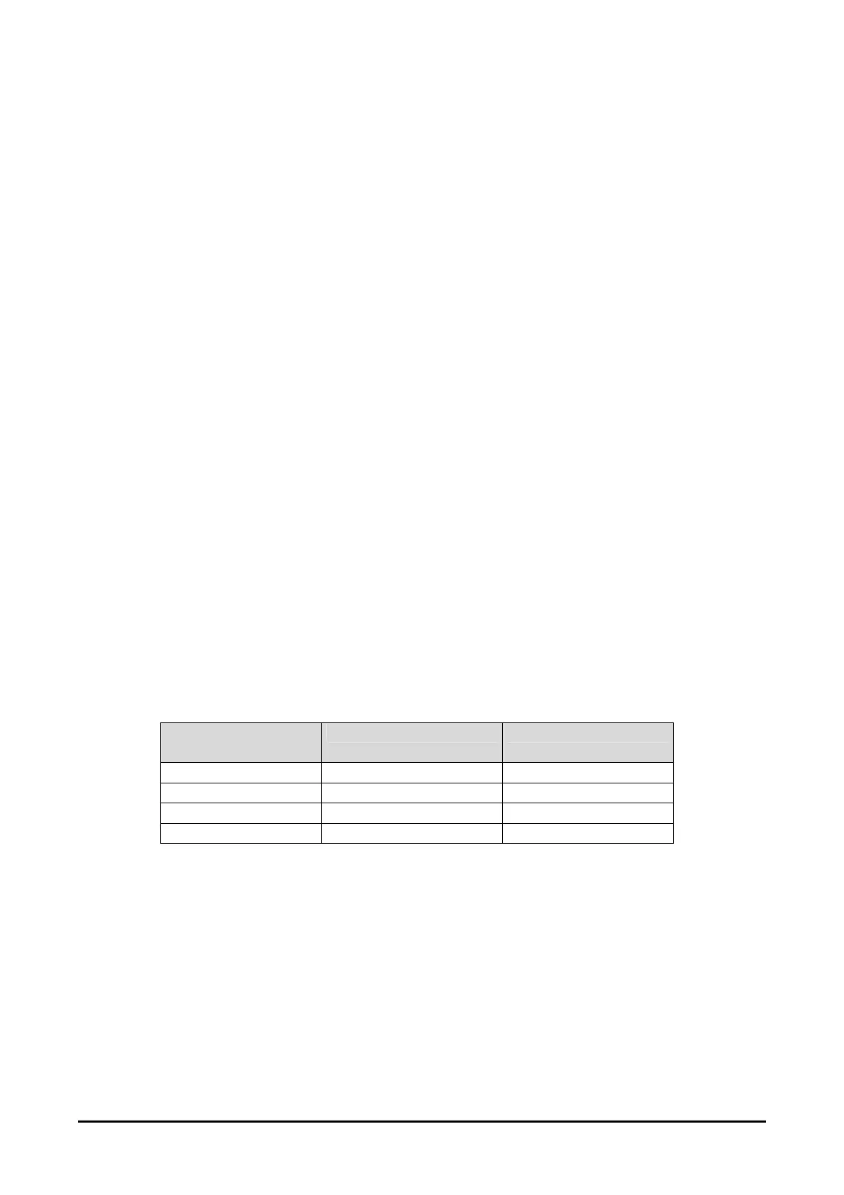
or the velocity (OPTION) measures. For various possible configurations see Table 3.
For analog outputs a voltage of 0.00Vcc is not obtainable as the transducer is supplied
with only positive voltage. The minimum voltage is about 50 mV (typical). These values
can be reduced by using the mass dedicated to it as a reference for the analog signal
(yellow wire or 5 pin, refer to chapter 10).
IMPORTANT NOTE: the outputs can only be positive and must be used paired: they can
be either voltage or current, but not mixed; it is not possible to match a current output with
a voltage one.
Number of
cursors
Output: A/D1 Output: A/D 2
1 One displacement -
1 One displacement One velocity
2 One displacement One displacement
2 One velocity One velocity
Table 3: possible analog output configurations
The direction of the cursor displacement signal detected in voltage or in current can be
modified by the User by means of RS485 throught external computer (recommended). In
the case of a voltage output of 0÷10 V It is possible to match the 10 V signal at full scale.
This setting of 0÷10 V can be inverted to 10÷0 V ( It is possible also to do the
personalisation for the current outputs).
For direction settings (if not specified in the order) see chapter 13.