Series PC Manual V 1.0 - Rev. 3 – 03/01/01 DS Europe
20
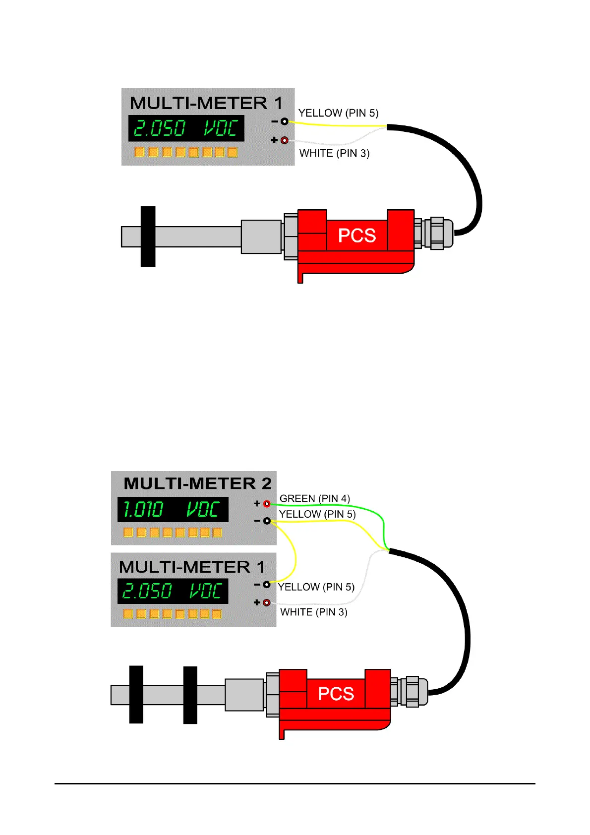
figure 7: Connection for analog voltage output
Note that for the analog signal negative, a separate YELLOW wire is used (PIN5) and not
the BLACK input negative (PIN2); this provision allows us to separate feedback signal
from the input and improve signal stability.
10.5. CONNECTION OF TWO VOLTAGE ANALOG OUTPUTS: 0÷10V
Connect the YELLOW wire (PIN5) to the negative of the multi-meteres or data acquisition
card. Connect the WHITE wire (PIN3) to the positive of the first multi-meter and the
GREEN wire (PIN4) to the positive of the second multi-meter.
figure 8: Electrical connection for two analog
voltage outputs.