Series PC Manual V 1.0 - Rev. 3 – 03/01/01 DS Europe
32
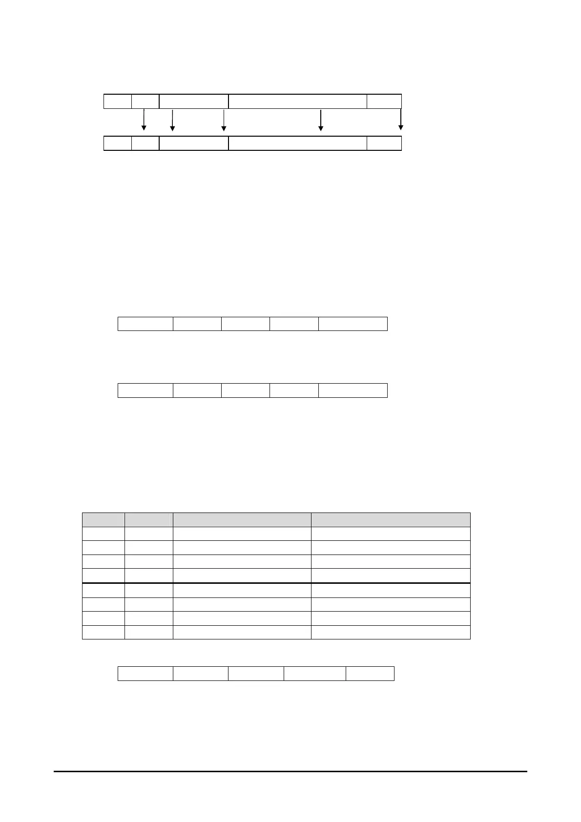
COMMAND MESSAGE STRUCTURE
@ ID COMMAND COMMAND SUBJECT <cr> Message structure
1 2 3 From 4 to n -1 n Character position
14.3. ACCEPTED COMMANDS
NOTE: The transducer recognises the command character sent, regardless of whether the
equivalent letter is capital or small.
Suppose there is to connect a transducer with ID “0”, the following commands could be
utilised:
14.3.1. COMMAND “A”
Command “A” allows to modify, or designate, the transducer identity (ID).
Accepted values are from “0” to “9” or “A” to “Z” (capital).
Example:
@ 0 A 1 <cr>
To confirm command execution, i.e. substitution of ID from 0 to 1, the transducer responds
with an exclamation mark “!”.
If you cannot remember the transducer ID, it is possible to connect up to it using the ?.
Example:
@ ? A 1 <cr>
14.3.2. COMMAND “D”
The command “D” allows to program the configuration byte of the D\A converters, thus
setting their way to operate.
The command can be summarised by the format “Dbbbbbbbb”, where “D” is the real true
command and “bbbbbbbb” are the 8 bits which make up the byte (each “b” can only be a
value “0” or the value “1”). The bits are numbered from right to left.
The first on the right is the number 0 ( sequence 7-6-5-4-3-2-1-0 ).
BIT D/A Bit VALUE = 0 Bit Value = 1
0 1 CURSOR 0 CURSOR 1
1 1 DISPLACEMENT VELOCITY
2 1 DIRECT INVERTED
3 1 OFF ON
4 2 CURSOR 0 CURSOR 1
5 2 DISPLACEMENT VELOCITY
6 2 DIRECT INVERTED
7 2 OFF ON
Table 3: D/A byte configuration
Example:
@ 0 D 10011000 <cr>
In the example, the D/A 2 (1001) converter is configured as on, direct, representing the
displacement measure for cursor 1 while the D/A 1 (1000) is configured as on, direct,
representing the displacement measurement for cursor 0.