Supervision
Relay
Optional
use of PGM
output (See
Programming)
WARNING:
Incorrect connections may result in PTC failure or improper operation. Inspect wiring and ensure connections are correct before turning on.
All circuits are classified for UL installations as Power Limited/Class II Power Limited. Do not route any wiring over circuit
boards. Maintain at least 1” (25.4mm) separation. A
minimum 1/4” (6.4mm) separation must be maintained at all points between Power Limited wiring and all other Non-Power Limited w
iring. Route wires as indicated in the diagram.
NOTE: For ULC Commercial Burglary Installation requirements please refer to Figure 5 and to the ULC Installation Guide P/N 29002157.
Telephone Line
Connection
RJ-45
For use in dry indoor ordinary locations only. For installation refer to NFPA70, 72.
Examples of control units/Subscribers Unit or power supplies compatible models:
DSC PC1864, HS2128, PC5204, HSM2204.
Electrical Ratings: 13.8 V
DC
/ 700 mA use ADP1310W-NAU/NA (US/CDN) and
Battery: 7.2V/2.2Ah
Electrical ratings: 9-14V
DC
/500mA use listed control panel or power supply
Alarm Control Panel with
Dialler Interface
(Supports Contact ID
format)
BATTERY
Sealed
Rechargeable
7.2V / 2.2Ah
RM1-UL Installations
RM1C-ULC Installations
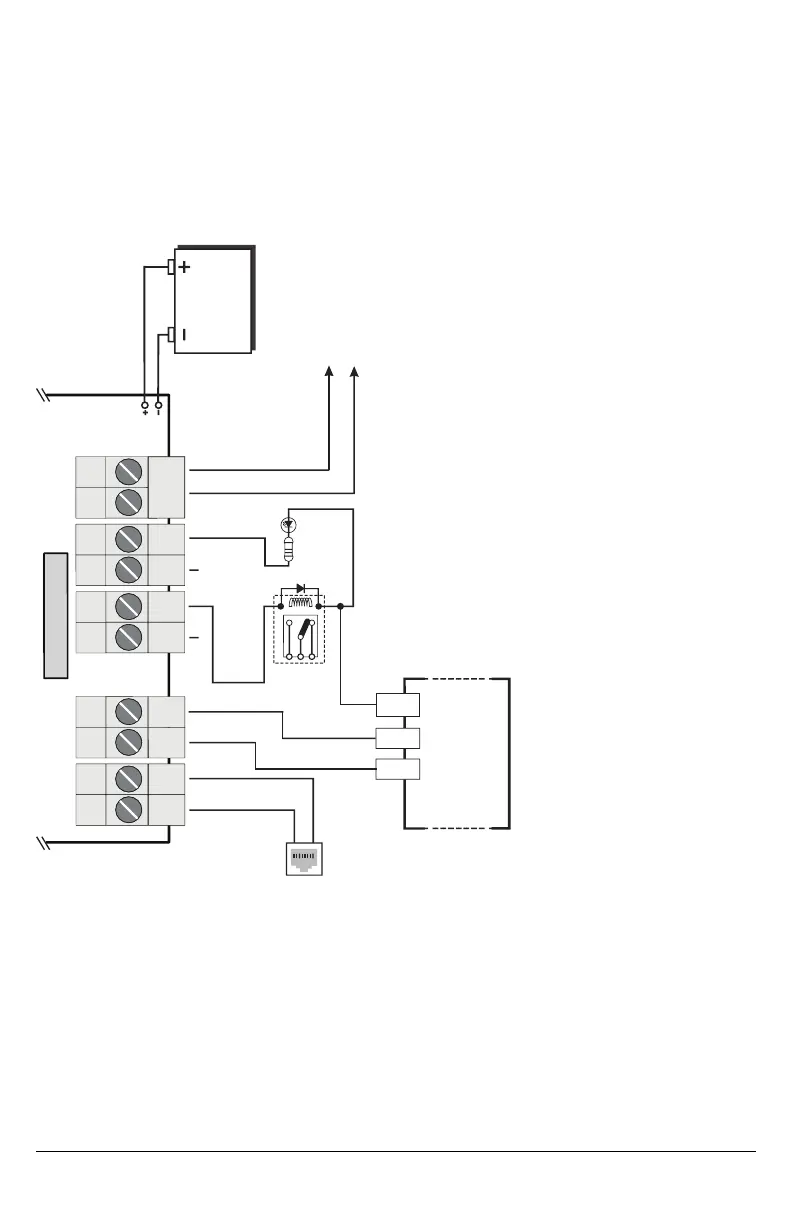
Connect relay contacts to a zone input on the alarm control
panel for LE4000 troubles supervision (24hr-type zone)
T
I
P
R
I
N
G
Panel Aux Power or External Power Supply AUX
Output of the control panel (which can power the
communicator) shall be rated LPS (power limited). Use only
power supplies that have AUX output isolated from EGND
Typical battery charge: 30-50 mA
Recommended Model: NiMH, Rated 7.2V, 2.2Ah
Use only: Model 6PH-H-AA2200-S-D22 from Great Power.
LE4000
TIP
RING
T1
R1
Z1
PGM1
Z2
PGM2
DC IN
+
-
1
2
3
4
5
6
7
9
8
10
WARNING!
HIGH VOLTAGE.
DISCONNECT DC
POWER AND
TELEPHONE LINES
PRIOR TO SERVICING.
Incorrect connections
may result in failure
or improper operation.
}
Inputs to be connected
to dry contact outputs
from alarm control panel
(Use No. 26 AWG
wires for the
connection to PSTN)
+12V
1K5
For UL Installations, the system shall be installed in accordance with chapter 2 of the ANSI/NFPA 72 and ANSI/NFPA70. Recommended loca-
tions and wiring methods shall be in accordance with the National Electrical Code, ANSI/NFPA 70, the Standard for Installation and Classifica-
tion of Burglar and Holdup Alarm Systems, UL 681, and the Standard for Central-Station Alarm Services, UL 827.
For ULC Installations, the recommended locations and wiring methods shall be in accordance with CSA C22.1, Canadian Electrical Code, Part
I, Safety Standard for Electrical Installations; CAN/ULC-S302, Installation and Classification of Burglar Alarm Systems for Financial and Com-
mercial Premises, Safes and Vaults; and CAN/ULC-S301, Standard for Central and Monitoring Station Burglar Alarm Systems and the Stan-
dard for the Installation of Residential Fire Warning Systems, CAN/ULC-S540. Do not install the equipment in places where the signal strength
does not meet the minium recomended signal strength level. Do not run zone inputs and T1/R1 wiring along AC wires or other circuits with high
frequency signals in order to reduce possibility of interference and false alarms.

 Loading...