Title: Micro
Doc No.: 018-1000-02
Description: Emergency Lighting Inverter User’s Manual Date: 07/26/2016
Rev: NR
1.877.DSPM.POWERPhone : 1.877.377.6769-
909.930.3335Fax:
www.dspmanufacturing.com
Website:
techsupport@dspmanufacturing.com
E-Mail:
Cabinet. The other two terminal blocks are for the optional alarm contacts to the battery cabinet. When making the
interconnection between the UPS Cabinet and the Battery Cabinet it is imperative that power connections being
connected observing all proper polarities?
5.2.B. SYSTEM COMPONENT LAYOUT
The following layouts will help you nd the parts and components in your Emergency Lighting Inverter. Maintenance
should only be performed by factory-trained or qualied personnel. Do not attempt to service. If you need technical
assistance, please contact DSPM.
5.2. DESCRIPTION OF UPS CABINET (S)
5.3. DESCRIPTION OF AC INPUT AND AC OUTPUT TERMINALS BLOCKS
The AC Input, AC Output Terminals Blocks are provided for the connection of incoming power and the connection of the
load (equipment) intended to be powered by the UPS. Refer to appropriate Component layout for these connections and
their locations in the UPS Cabinet.
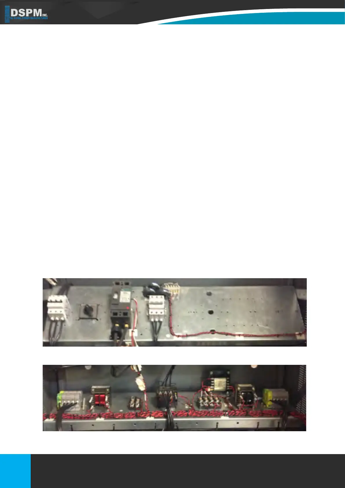
Figure 7b Center Shelf (Input Terminal Block on le)
Figure 7a Main Breaker Shelf
5.4. MANUAL BYPASS SWITCH DESCRIPTION
In most units, this switch is located on the inside of the left door of the system (See system component diagram for exact
location). The bypass switch is used in case of a failure of the lighting inverter. If the lighting inverter fails, place the bypass
switch in the “MAN” position. In this position the inverter section is bypassed allowing the load to be powered by the utility
until the inverter can be repaired. In case of system failure, contact factory for service. The Manual Bypass Switch is used
to bypass the electronic (inverter) when the system have failed. The Manual Bypass Switch should never be operated
when the UPS is supporting the load. The rotation of this switch will turn off the inverter. The Load will be fed from the Utility
until the switch is place back into the UPS position, and the inverter is returned back to operation.
25
Title: Three Phase 208 or 208Y/120Vac
Doc No.: 018-6000-00
Description: Emergency Lighting Inverter User’s Manual
Rev: NR
Date: 08/12/2022
Phone :
Website:
E-Mail:
Fax:
1.877.DSPM.POWER-1.877.377.6769
1.877.DSPM.POWER-1.877.377.6769
www.dspmanufacturing.com
techsupport@dspmanufacturing.com