equipment.
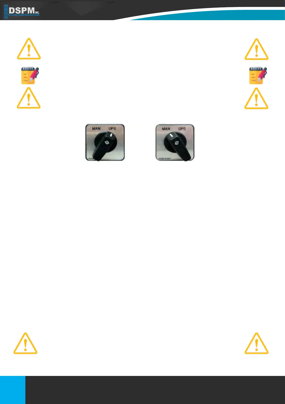
The manual bypass switch should only be operated by authorized person-
nel.
Operation of the bypass switch will cause the inverter switch to static bypass and turn
off the inverter if it was running.
5.5. INPUT AND OUTPUT POWER REQUIREMENTS/CONNECTIONS
After unpacking and inspecting the Inverter System for shipping damage and reporting any such damage to the carrier, it is
vital that the input power be connected correctly at the required voltages. It is highly recommended that a qualied electrician
make all input and output power connections. It is vital that a true ground be brought into the unit, not a neutral. The ground
conductor should be the same size as the two input / primary voltage phase conductors. The input power connections to the
UPS come from building supplied services.
5.6. SYSTEM CURRENT RATINGS
All circuit breakers provided by the end user that are connected to the inputs and outputs, need to be of the “High Inrush” type.
This is to prevent the breakers from tripping during the startup of the unit and its load. DSPM uses only the “High Inrush” type
of breaker in its units. Refer to Figure 8 when determining the size of your input and output breakers.
5.7. GROUNDING
The Ground Terminals centralize the system grounds for routing back to the building service entry panel and the output load.
The equipment grounding electrode terminals are all tied to a single point within the cabinet along with all grounds from within
the UPS cabinet. This single point functions as a true, single-point ground. The output neutral point, equipment ground, trans-
former core, cabinet and system ground are all tied together at one point.
DO NOT CONNECT THE UPS GROUND WIRE TO ANY FORM OF AN ISO-
LATED GROUND SYSTEM. SUCH A CONNECTION WOULD RESULT IN
A SAFETY HAZARD, AND UNDER GROUND FAULT CONDITIONS OR
LIGHTNING STRIKES, MAY CAUSE SEVERE SYSTEM DAMAGE.
Title: Micro
Doc No.: 018-1000-02
Description: Emergency Lighting Inverter User’s Manual Date: 07/26/2016
Rev: NR
1.877.DSPM.POWERPhone : 1.877.377.6769-
909.930.3335Fax:
www.dspmanufacturing.com
Website:
techsupport@dspmanufacturing.com
E-Mail:
26
Normal Operation Bypass Operation
Figure 8
Title: Three Phase 208 or 208Y/120Vac
Doc No.: 018-6000-00
Description: Emergency Lighting Inverter User’s Manual
Rev: NR
Date: 08/12/2022
Phone :
Website:
E-Mail:
Fax:
1.877.DSPM.POWER-1.877.377.6769
1.877.DSPM.POWER-1.877.377.6769
www.dspmanufacturing.com
techsupport@dspmanufacturing.com