Title: Micro
Doc No.: 018-1000-02
Description: Emergency Lighting Inverter User’s Manual Date: 07/26/2016
Rev: NR
1.877.DSPM.POWERPhone : 1.877.377.6769-
909.930.3335Fax:
www.dspmanufacturing.com
Website:
techsupport@dspmanufacturing.com
E-Mail:
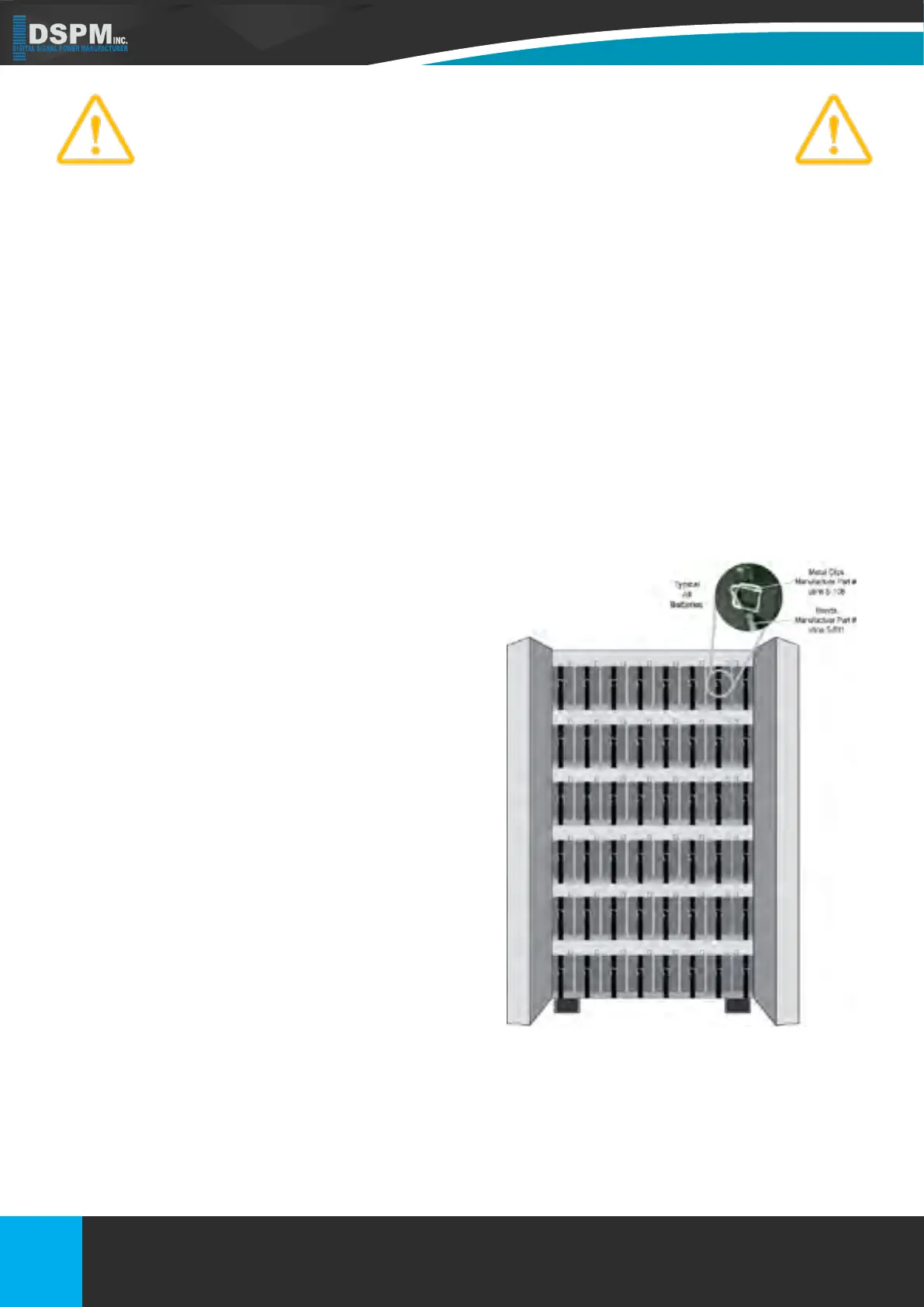
Each battery cabinet may contain one or more strings of batteries. Each string has a quantity of 20 batteries. The
battery placement per shelf depending on the amp-hour or the batteries used. The amp-hour of the batteries is deter-
mined by the number of batteries in a string and the runtime of the inverter when the utility is lost. When necessary the
alley areas between the cabinet and the shelf will be used (refer to Figure 10).
There are battery-to-battery jumpers and shelf-to shelf battery jumpers provided. The shelf-to-shelf jumpers are stan-
dardized to cover many power levels. The battery-to-battery jumpers are the same gauge or smaller as the shelf-to-
shelf battery jumpers.
Installation starts by connecting the positive shelf-to-shelf battery jumper.
After creating each string of batteries, ensure that each string (Each string is either 44 or 45 batteries total) consist of
the number of batteries indicated by the battery layout and the measured voltage from the rst to the last battery is
within the voltage range stated above.
Be careful not to touch or ground yourself or tools to anything while installing jumpers!). As
each battery is placed, install the battery to battery jumpers until all batteries are installed
on the shelf. Finally connect the negative shelf-to-shelf jumper to complete the battery shelf
installation (Refer to Figure 10 for the individual shelf and a whole cabinet).
The rst and last battery of each string are then connected
to the isolation breakers in the right-side battery cabinet
door. See attached image-general breaker arrangement.
The battery cabinet shelf-to-circuit breaker jumpers are
pre-wired into the cabinet. The installer measures the
DC voltage across each circuit breaker to verify polarity
and voltage after battery installation. If the polarity and
voltage are correct, then the terminal blocks above the
breakers provide for wiring each string back to the inverter
cabinet. The inverter cabinet parallels the strings. The in-
verter cabinet has multiple battery string terminal blocks.
Refer to System Component Layout. The number match-
es the number of strings coming back from the battery
cabinets. For example, if there are four strings over two
battery cabinets, then a total of eight cables run back from
the battery cabinets to the inverter cabinet. Each cabinet
would have four wires, two negative and two positive com-
ing from it. The positive and negative terminal blocks in
the inverter cabinet are grouped by polarity. This ensures
positive and negative string connections are not inadver-
tently shorted together.
28
Figure 10 – Whole Cabinet – Two
Strings of 45 Batteries
Title: Three Phase 208 or 208Y/120Vac
Doc No.: 018-6000-00
Description: Emergency Lighting Inverter User’s Manual
Rev: NR
Date: 08/12/2022
Phone :
Website:
E-Mail:
Fax:
1.877.DSPM.POWER-1.877.377.6769
1.877.DSPM.POWER-1.877.377.6769
www.dspmanufacturing.com
techsupport@dspmanufacturing.com