Title: Micro
Doc No.: 018-1000-02
Description: Emergency Lighting Inverter User’s Manual Date: 07/26/2016
Rev: NR
1.877.DSPM.POWERPhone : 1.877.377.6769-
909.930.3335Fax:
www.dspmanufacturing.com
Website:
techsupport@dspmanufacturing.com
E-Mail:
6.2. INPUT POWER CONNECTIONS
It is highly recommended that a qualied electrician make all input power connections. The input power should be connect-
ed correctly at the required voltages and the ground cable should be of the same gauge as the input power cables. Ensure
that the utility power to be connected is rated as on the system label. Make sure the hots, neutral and grounds are correctly
identied and wired to the input terminal block as designated.
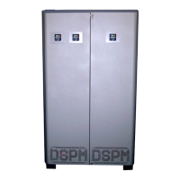
The input power connections to the UPS come from the building supplied services. These connections are made inside the
UPS cabinet (refer to Figure 12, System Component Layout). The input cables are connected to a three (3) pole terminal
block(TB1) which is comprised of one (1) input power, neutral, and ground connections.
6.3. OUTPUT POWER CONNECTIONS
It is highly recommended that a qualied electrician make all input power connections. The output power should be connect-
ed correctly at the required voltages and the ground cable should be of the same gauge as the output power cables. Ensure
that the loads to be connected are as listed on the system label, and the hots, neutral and grounds are correctly identied
and are wired to the output terminal block as designated. Loads not powered by the system cannot use the neutral of the
Emergency Lighting Inverter System.
These connections are made inside the UPS cabinet in one of two ways, depending on whether the unit is a 50 or a 150KVA
(refer to the proper System Component Layout). In the 50KVA, the output cables are connected to a ve (5) pole terminal
block(TB1) which is comprised of three (3) output power, neutral, and ground connections. In the 150KVA the output cables
are connected to the Output Circuit Breaker CB4 and an adjacent chassis grounding terminal block (TB2). The Output
Power Connections are comprised of three (3) output power connections and a chassis ground. The output over current
DO NOT BOND THE OUTPUT NEUTRAL TO CHASSIS GROUND!
THE SYSTEM HAS BEEN BONDED AS REQUIRED BY THE MANU-
FACTURER AND NATIONAL ELECTRICAL CODE.
29
Each cabinet string has a separate run back to the inverter cabinet. Each cabinet string should be brought on line one
at a time by setting the string’s circuit breaker to the ON position. Verify that the breaker does not trip, since that would
indicate a swapped string connection. If you have any further questions about battery connections please contact
DSPM Service Department: at 1(877)377-6769.
6.1.A. CHARGING OF THE BATTERIES: The Emergency Lighting Inverter System charges its battery whenever it is
connected to utility power and the input circuit breakers (CB1) is turned on. Disconnect charging source prior to con-
necting or disconnecting battery terminals. For the best results, charge the battery for 24 hours after they are hooked
up and the ELI is brought on line.
Title: Three Phase 208 or 208Y/120Vac
Doc No.: 018-6000-00
Description: Emergency Lighting Inverter User’s Manual
Rev: NR
Date: 08/12/2022
Phone :
Website:
E-Mail:
Fax:
1.877.DSPM.POWER-1.877.377.6769
1.877.DSPM.POWER-1.877.377.6769
www.dspmanufacturing.com
techsupport@dspmanufacturing.com