Figure 12
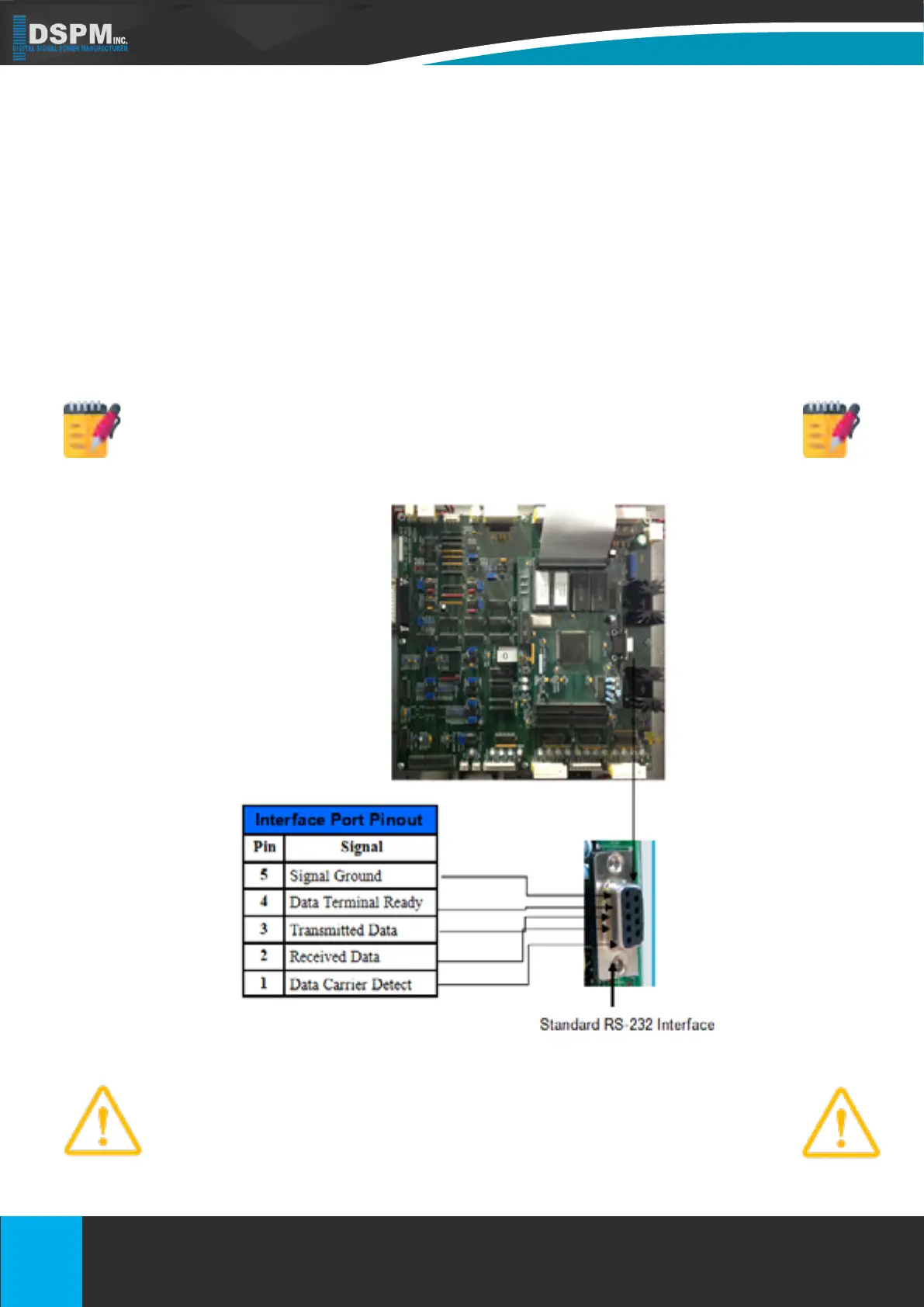
6.4. COMMUNICATIONS INTERFACE
Software interface kits can be used with this Emergency Lighting Inverter System. The RS-232 interface uses a
9-pin female D-sub connector. The information provided to the connector consists of data about utility, load, and
the Emergency Lighting Inverter System. The interface port pins and their functions are identied in the Figure
12. Contact the factory for optional kits supplied or approved by DSPM. If used, connect the interface cable to
the 9-pin computer interface port (RS-232 Standard Interface Port) on the Main PCB Control Board in the door
(refer to Figure 12) of the Emergency Lighting Inverter System.
Software Interface Kit’s connection is optional. The Emergency Lighting Inverter Sys-
tem works properly without an optional interface connection. Use only factory supplied
or authorized Emergency Lighting Inverter System monitoring cable!
CAUTION: Use only factory supplied or authorized Emergency Lighting Inverter System
monitoring cable!
33
Title: Micro
Doc No.: 018-1000-02
Description: Emergency Lighting Inverter User’s Manual Date: 07/26/2016
Rev: NR
1.877.DSPM.POWERPhone : 1.877.377.6769-
909.930.3335Fax:
www.dspmanufacturing.com
Website:
techsupport@dspmanufacturing.com
E-Mail:
Title: Three Phase 208 or 208Y/120Vac
Doc No.: 018-6000-00
Description: Emergency Lighting Inverter User’s Manual
Rev: NR
Date: 08/12/2022
Phone :
Website:
E-Mail:
Fax:
1.877.DSPM.POWER-1.877.377.6769
1.877.DSPM.POWER-1.877.377.6769
www.dspmanufacturing.com
techsupport@dspmanufacturing.com